原文:Report ITU-R BT.2408-9 (03/2026) — Guidelines for operational practices in high dynamic range television production
报告:ITU-R BT.2408-9(2026 年 3 月)
BT 系列:广播业务(电视)
作者:国际电信联盟无线电通信局(ITU-R)
版本沿革:2017-2018-04/2019-07/2019-2021-2022-03/2023-09/2023-2024-2026
翻译:Horace Lu
摘要
These guidelines for operational practices are intended to help ensure optimum and consistent use of high dynamic range in television production using the Perceptual Quantization (PQ) and Hybrid Log-Gamma (HLG) methods specified in Recommendation ITU-R BT.2100. Additional background information on HDR is available in Report ITU-R BT.2390, while Report ITU-R BT.2446 provides guidance towards the design of methods of conversion between HDR and SDR content.
本操作实践指南旨在帮助电视制作以最优、一致的方式运用高动态范围,所用的是建议书 ITU-R BT.2100 规定的感知量化(PQ)和混合对数伽马(HLG)两种方法。关于 HDR 的更多背景信息见报告 ITU-R BT.2390;报告 ITU-R BT.2446 则就 HDR 与 SDR 内容之间转换方法的设计提供指导。
目录
- 1 引言
- 2 参考电平与信号格式
- 3 监看
- 4 图像亮度
- 5 标准动态范围与高动态范围制作的融合
- 6 PQ 与 HLG 之间的转换
- 7 从 SDR 制作向 HDR 制作过渡
- 8 相机与显示设备 RGB 色度学的转换实践
- 9 图形
- 附件 1 — 评估 PQ 内容电平的研究
- 附件 2 — 参考电平分析
- 附件 3 — 肤色的两项研究:基于反射率数据库与基于真人
- 附件 4 — 广播内容中面部肤色的研究
- 附件 5 — PQ 的显示——EETF 的计算
- 附件 6 — HDR 与 SDR 制作原生观感的比较
- 附件 7 — 归一化基色矩阵的计算
- 附件 8 — 中国的 4K/8K UHD HDR 与 HD SDR 同制同播实践
- 附件 9 — 近距离并置的 HDR 与 SDR 监视器
- 附件 10 — NBCUniversal 的单母版 HDR-SDR 工作流
- 附件 11 — 203 cd/m² 与 100 cd/m²(BT.2035)SDR 信号格式之间的转换
- 参考文献
- 术语表
1 Introduction
1 引言
Recommendation ITU-R BT.2100 (BT.2100) specifies HDR-TV image parameters for use in production and international programme exchange using the Perceptual Quantization (PQ) and Hybrid Log-Gamma (HLG) methods. Since its first publication in 2016, television programme production in high dynamic range (HDR) continues to grow and is attracting increasing interest from content creators and broadcasters wishing to benefit from the improved viewing experience that HDR offers. At the same time, standard dynamic range (SDR) and high dynamic range will need to coexist for many years to come. These operational practices propose guidance to programme makers and broadcasters based on knowledge and practical experience gained so far. A glossary of terms is included at the end of this Report.
建议书 ITU-R BT.2100(下称 BT.2100)规定了用于制作与国际节目交换的 HDR 电视图像参数,所用方法为感知量化(PQ)和混合对数伽马(HLG)。自 2016 年首次发布以来,高动态范围(HDR)电视节目制作持续增长,越来越多希望借 HDR 改善观看体验的内容创作者和广播机构对此产生兴趣。与此同时,标准动态范围(SDR)与高动态范围在今后许多年里仍须并存。本操作实践基于迄今积累的知识和实践经验,为节目制作者和广播机构提供指导。本报告末尾附有术语表。
Production in PQ is similar to standard dynamic range production. During capture, the scene may be exposed to produce the desired appearance on a reference monitor, ideally operating in the reference environment. Exposure setting may be assisted for example by setting a grey or diffuse white card to the desired signal level. It is possible for the PQ system to capture and encode information that is beyond the capabilities of a specific monitor, if that monitor cannot reach both the ideal peak luminance of 10 000 cd/m2 and the full extent of the BT.2100 wide colour gamut. If the PQ signal is not actively constrained to the capability of the reference monitor in use, more information may be revealed on a subsequent display with higher peak luminance or colour gamut.
用 PQ 制作与标准动态范围制作相似。拍摄时,可对场景曝光,使其在参考监视器(理想情况下工作于参考环境)上呈现理想观感。设定曝光时,可借助一些手段,例如把灰卡或漫反射白卡设到理想的信号电平。如果某台监视器达不到 10 000 cd/m² 的理想峰值亮度,也覆盖不了 BT.2100 宽色域的全部范围,那么 PQ 系统所采集和编码的信息有可能超出这台监视器的能力。若不主动把 PQ 信号约束到所用参考监视器的能力之内,那么在日后峰值亮度更高或色域更宽的显示设备上,就可能呈现出更多信息。
HLG has been designed to enable a straightforward migration towards HDR television production, with few changes to SDR production working practices. The compatible nature of the HLG signal allows standard dynamic range monitors to be used in non-critical monitoring areas. HDR monitors are necessary only for critical monitoring, such as when colour grading, camera shading and monitoring programme and preview outputs in a production gallery.
HLG 的设计意在让人能够顺畅地迁移到 HDR 电视制作,对 SDR 制作的工作方式几乎无须改动。HLG 信号的兼容特性,使标准动态范围监视器可用于非关键监看区。只有关键监看才需要 HDR 监视器,例如调色、摄像机明暗控制(shading),以及在制作机房监看节目输出和预览输出时。
Just as line-up levels are useful for audio production, nominal signal levels for standard test charts are also useful for HDR television production. Nominal signal levels are given in order to facilitate camera line-up to help ensure consistency both within and between programmes, together with advice on monitoring and displaying HDR content.
正如校线电平对音频制作很有用,标准测试图卡的标称信号电平对 HDR 电视制作同样有用。本报告给出标称信号电平,以便相机校线,帮助确保节目内部及节目之间的一致性,同时给出监看和显示 HDR 内容的建议。
Initial findings are presented on viewer tolerances to variations in image brightness, aimed in particular at avoiding viewer discomfort at junctions between programmes and other items of content, as well as when switching between programme channels.
本报告还给出关于观众对图像亮度变化容忍度的初步发现,重点在于避免观众在节目与其他内容衔接处、以及切换频道时感到不适。
Techniques are described for including SDR content in HDR productions, as are the principles of transcoding between PQ and HLG. Experience gained from trials with live production is documented, offering a practical guide for transitioning from SDR to HDR.
报告介绍了在 HDR 制作中纳入 SDR 内容的技术,以及 PQ 与 HLG 之间转码的原理,并记录了直播制作试验中积累的经验,为从 SDR 向 HDR 过渡提供实用指南。
Annexes provide further technical details and background information. Annexes 1, 2, 3 and 4 present the results of studies analysing skin tones and other existing content which have been used to help inform guidance on video levels in HDR production (see § 2.2).
各附件提供更多技术细节和背景信息。附件 1、2、3、4 给出了分析肤色及其他现有内容的研究结果,这些研究为 HDR 制作中视频电平的指导提供了依据(见 2.2 节)。
Annex 5 compares various approaches that can be used to map PQ signals to displays with a lower dynamic range than contained in the signal; such processes may also be required during conversion from PQ to HLG (see §§ 3.1.1 and 6.4).
附件 5 比较了把 PQ 信号映射到动态范围低于信号本身的显示设备上的各种方法;由 PQ 转换为 HLG 时也可能需要这类处理(见 3.1.1 节和 6.4 节)。
Annex 6 compares the native displayed ‘look’ of each SDR and HDR production format (see §§ 5.2 and 7.6.3).
附件 6 比较了 SDR 与 HDR 各制作格式原生显示的“观感”(见 5.2 节和 7.6.3 节)。
Annex 7 gives technical details on how to calculate the normalized primary matrix (NPM) needed for conversion to and from the CIE XYZ colour space and the BT.2100 colour space (see § 8).
附件 7 给出技术细节,说明如何计算在 CIE XYZ 色彩空间与 BT.2100 色彩空间之间相互转换所需的归一化基色矩阵(NPM)(见第 8 节)。
Annex 8 describes, as an example, practical experience with the 4K/8K UHD HDR and HD SDR simul-production and simulcast methods used in China (see § 7.3.2).
附件 8 以中国采用的 4K/8K UHD HDR 与 HD SDR 同制同播方法为例,介绍其实践经验(见 7.3.2 节)。
Annex 9 describes two approaches to the use of HDR and SDR monitors in situations where close proximity cannot be avoided.
附件 9 介绍在 HDR 与 SDR 监视器无法避免近距离并置时的两种处理方法。
Annex 10 describes a new approach, used by some broadcasters in the USA, whereby SDR shading monitors in live HDR production are operated at 203 cd/m2 rather than the usual 100 cd/m2 nominal peak luminance. Annex 11 describes how the resulting SDR signals may be converted to the 100 cd/m2 SDR signal format for Recommendation ITU-R BT.2035 programme exchange.
附件 10 介绍美国部分广播机构采用的一种新方法:在 HDR 直播制作中,把 SDR 明暗控制监视器按 203 cd/m² 而非常见的 100 cd/m² 标称峰值亮度来运行。附件 11 则说明如何把由此得到的 SDR 信号转换为 100 cd/m² 的 SDR 信号格式,以用于建议书 ITU-R BT.2035 的节目交换。
2 Reference levels and signal format
2 参考电平与信号格式
During set-up, camera controls such as gain and shutter and others may be pre-adjusted to make best use of camera sensor capabilities, i.e. a balance between signal to noise ratio (SNR) and achieved sensor peak capability, and to establish a creative intent. During capture, the exposure may then be adjusted taking consideration of the reference levels listed below as well as the creative intent.
在架设阶段,可预先调整增益、快门等相机控制项,以充分发挥相机传感器的能力——即在信噪比(SNR)与传感器所能达到的峰值能力之间取得平衡——并确立创作意图。拍摄时,再综合考虑下文所列参考电平与创作意图来调整曝光。
2.1 HDR Reference White
2.1 HDR 参考白
The reference level, HDR Reference White, is defined in this Report as the nominal signal level obtained from an HDR camera and a 100% reflectance white card resulting in a nominal luminance of 203 cd/m2 on a PQ display or on an HLG display that has a nominal peak luminance capability of 1 000 cd/m2. That is the signal level that would result from a 100% Lambertian reflector placed at the centre of interest within a scene under controlled lighting, commonly referred to as diffuse white1. There may be brighter whites captured by the camera that are not at the centre of interest and may therefore be brighter than the HDR Reference White.
本报告把参考电平“HDR 参考白”定义为:用 HDR 相机对着一张 100% 反射率白卡所得到的标称信号电平,它在 PQ 显示设备上、或在标称峰值亮度能力为 1 000 cd/m² 的 HLG 显示设备上,对应 203 cd/m² 的标称亮度。这也就是在受控照明下,把一个 100% 朗伯反射体置于场景兴趣中心处所产生的信号电平,通常称为漫反射白[1]。相机也可能采集到不位于兴趣中心、因而比 HDR 参考白更亮的白。
Graphics White is defined within the scope of this Report as the equivalent in the graphics domain of a 100% reflectance white card: the signal level of a flat, white element without any specular highlights within a graphic element. It therefore has the same signal level as HDR Reference White, and graphics should be inserted based on this level.
本报告把图形白定义为图形领域中相当于 100% 反射率白卡的对应物:即图形元素中一块平整、不含任何镜面高光的白色区域的信号电平。因此它与 HDR 参考白的信号电平相同,图形应以此电平为准插入。
The nominal signal level corresponding to HDR Reference White, diffuse white and Graphics White is shown in Table 1.
HDR 参考白、漫反射白和图形白所对应的标称信号电平见表 1。
Signal levels for common test charts and reflectance cards with different reflectance are calculated using scene-light (the light falling on a camera sensor), from HDR Reference White. Details are given in § 2.2.
各种常见测试图卡和不同反射率反射卡的信号电平,是从 HDR 参考白出发、按场景光(落在相机传感器上的光)计算得到的。详见 2.2 节。
2.2 Signal levels for line-up in production
2.2 制作中用于校线的信号电平
Signal levels in these operational practices are specified in terms of %PQ and %HLG. These percentages represent signal values that lie between the minimum and maximum non-linear values normalized to the range 0 to 1.
本操作实践中的信号电平以 %PQ 和 %HLG 表示。这些百分数代表归一化到 0 至 1 范围内、介于非线性最小值与最大值之间的信号值。
The values in Table 1 are presented as nominal recommendations for test charts and graphics for PQ production and for HLG production on a 1 000 cd/m2 (nominal peak luminance) display, under controlled studio lighting2. They assume no artistic adjustments have been made through camera painting controls or in post-production. In practice that may not be the case. While to facilitate HDR/SDR format conversion it is common practice to adhere to the reference level ‘HDR Reference White’, the signal levels for grey cards and skin tones (Table 2) may vary.
表 1 中的数值,是针对受控演播室照明下[2]、用于 PQ 制作以及在 1 000 cd/m²(标称峰值亮度)显示设备上进行 HLG 制作的测试图卡和图形所给出的标称推荐值。它们假定未通过摄像机调校(painting)控制项或在后期作任何艺术性调整;实际中未必如此。为便于 HDR/SDR 格式转换,惯常做法是恪守“HDR 参考白”这一参考电平,但灰卡和肤色的信号电平(表 2)可能有所不同。
For PQ, the nominal luminance values are consistent on PQ reference displays. For HLG, the nominal luminance values will differ from those in Table 1 when the display’s peak luminance is lower or higher than 1 000 cd/m2. The nominal signal levels in Table 1 do not change. There is a practical benefit to the use of common levels for both PQ and HLG and Table 1 reflects guidance to use common levels. However, as PQ and HLG have different capabilities, and as HLG levels are influenced by a desire to maintain a degree of compatibility with SDR displays and PQ levels are not, as experience is developed in the use of both PQ and HLG this guidance to use common levels may need to be adjusted. Annex 1 describes a study of early HDR movies graded on a 4 000 cd/m2 PQ monitor. According to that study, luminance levels for indoor scenes were found to be typically about two thirds of the values indicated in Table 1, however those for outdoor scenes were found to be brighter. As producers of PQ content gain more experience, it is possible that levels in PQ indoor content may increase.
对 PQ 而言,标称亮度值在 PQ 参考显示设备上是一致的。对 HLG 而言,当显示设备的峰值亮度低于或高于 1 000 cd/m² 时,标称亮度值就会偏离表 1;但表 1 中的标称信号电平不变。让 PQ 与 HLG 共用同一套电平有实际好处,表 1 即体现了共用电平的指导原则。不过,PQ 与 HLG 能力不同,HLG 电平受到“需与 SDR 显示设备保持一定兼容性”这一考虑的影响,而 PQ 电平则不受此约束;因此随着 PQ 与 HLG 使用经验的积累,这条共用电平的指导原则或许需要调整。附件 1 介绍了一项研究,对象是在 4 000 cd/m² PQ 监视器上调色的早期 HDR 电影。据该研究,室内场景的亮度电平通常约为表 1 数值的三分之二,而室外场景则更亮。随着 PQ 内容制作者经验增多,PQ 室内内容的电平有可能上升。
It is important to know the reflectance of greyscale charts and white cards, to ensure that cameras are aligned to deliver the appropriate signal level and consistency in production.
了解灰阶图卡和白卡的反射率很重要,这样才能确保相机校准到位,输出合适的信号电平并在制作中保持一致。
An 18% grey card is commonly used for camera set-up in non-live workflows as it is the closest standard reflectance card to skin tones. It may also be useful when trying to match SDR and HDR cameras as the 18% grey should not be affected by any SDR camera ‘knee’. However, as the 18% grey card is close to ‘middle grey’ (i.e. halfway between black and diffuse white on a lightness scale) it is likely to be affected by camera painting in live production or colour grading in non-live production. So, the nominal signal levels for the 18% grey card will likely vary once artistic adjustments have been applied.
18% 灰卡常用于非直播工作流中的相机架设,因为它是最接近肤色的标准反射率卡。它在匹配 SDR 与 HDR 相机时也可能有用,因为 18% 灰应当不受任何 SDR 相机“拐点”的影响。不过,由于 18% 灰卡接近“中灰”(即在明度刻度上处于黑与漫反射白之间的中点),它很可能在直播制作中受摄像机调校、或在非直播制作中受调色的影响。因此,一旦施加了艺术性调整,18% 灰卡的标称信号电平就很可能发生变化。
A 75%-HLG or 58%-PQ marker on a waveform monitor, representing the reference level, will help the camera shader ensure that objects placed at the centre of interest within a scene are placed within the appropriate signal range, and that sufficient headroom is reserved for specular highlights.
在波形监视器上设一条代表参考电平的 75%-HLG 或 58%-PQ 标线,可帮助视频控制员确保场景兴趣中心处的物体落在合适的信号范围内,并为镜面高光保留足够的余量。
表 1. PQ 与 HLG 制作的标称电平
| 反射物体或参考(亮度因数,%)[3] | 标称亮度,cd/m²(PQ 参考显示设备,或 1 000 cd/m² HLG 显示设备) | %PQ | %HLG |
|---|---|---|---|
| 灰卡(18%)⁽¹⁾ | 26 | 38 | 38 |
| 灰阶图卡最高级(83%) | 162 | 56 | 71 |
| 灰阶图卡最高级(90%) | 179 | 57 | 73 |
| 参考电平:HDR 参考白(100%)⁽²⁾,亦即漫反射白与图形白 | 203 | 58 | 75 |
(1) The actual signal levels for an 18% grey card may differ significantly where camera painting controls have been applied.
(2) The signal level of ‘HDR Reference White’ is not directly related to the signal level of SDR ‘peak white’.
注⑴:施加摄像机调校控制后,18% 灰卡的实际信号电平可能有显著差异。
注⑵:“HDR 参考白”的信号电平与 SDR“峰值白”的信号电平没有直接关系。
In an experiment described in full in Annex 2, the levels of white objects in different types of HDR content were assessed, including an early live shoot of a baseball game, as well as a collection of HDR still photographs. In both cases, the mean white level is consistent with the HDR Reference White level as given in Table 1. However, for both types of content the spread around this mean value is significant, indicating that in practice the measured white levels can be expected to vary significantly around this target value.
附件 2 完整描述了一项实验,评估了不同类型 HDR 内容中白色物体的电平,内容包括一场棒球比赛的早期直播拍摄,以及一批 HDR 静态照片。两种情形下,白的均值电平都与表 1 给出的 HDR 参考白电平一致。然而,两类内容围绕该均值的离散度都很大,表明实际中所测得的白电平预计会在这一目标值上下有显著波动。
When test charts are either not available or impractical, other objects such as skin tones or grass are often used to set signal levels. Approximate signal levels are given in Table 2.
当测试图卡不可用或不便使用时,常用肤色、草地等其他物体来设定信号电平。近似的信号电平见表 2。
The Fitzpatrick Skin Tone Scale [1] is used to classify skin types, which will vary by region. It was originally developed as a way to estimate the response of different types of skin to ultraviolet light. It may be used to provide a convenient classification method for the range of skin tones seen in television production.
菲茨帕特里克肤色量表 [1] 用于划分肤型,肤型因地域而异。该量表最初是为估计不同类型皮肤对紫外线的反应而提出的,可为电视制作中所见的各种肤色提供一种便捷的分类方法。
Annex 3 describes how both experimental data, and a theoretical model of an ideal HDR television camera, have been used to determine the expected signal ranges for the Fitzpatrick skin types illustrated in Table 2. These ranges assume that content has been produced using the HDR Reference White signal levels specified in Table 1.
附件 3 介绍了如何利用实验数据以及一台理想 HDR 电视相机的理论模型,来确定表 2 所列各菲茨帕特里克肤型的预期信号范围。这些范围假定内容是按表 1 规定的 HDR 参考白信号电平制作的。
Annexes 1 and 4 report on skin tones in broadcast SDR content produced in studios in different regions. The skin tones in SDR content were found to be much different by regions. This may be mainly due to a difference in long-standing production practice for SDR rather than a difference in skin reflectance. Annex 4 also reports on a study on skin tones in HLG HDR content with camera shading compliant to the reference level of 75% HLG in comparison with SDR content, both produced independently for the same programme. The facial skin tones in the HLG content correspond to the Type 3-4 (medium skin tone) in Table 2.
附件 1 和附件 4 报告了不同地域演播室所制作广播 SDR 内容中的肤色。研究发现,SDR 内容中的肤色因地域而大不相同。这可能主要源于各地长期以来 SDR 制作实践的差异,而非皮肤反射率的差异。附件 4 还报告了一项研究:把摄像机明暗控制符合 75% HLG 参考电平的 HLG HDR 内容与 SDR 内容相比较,两者是为同一档节目各自独立制作的。该 HLG 内容中的面部肤色对应表 2 中的第 3—4 型(中等肤色)。
Variations in these signal levels can be expected. The value for grass, for example, will depend on the type of grass planted for a given sport, changing ambient lighting conditions during the day and between daytime and evening/night-time, as well as regional and producer preferences. In Europe, Association football (soccer) grass is typically reproduced correctly with an HLG signal level of 40%, corresponding to the well-established level of 50% SDR after display-light down-mapping for a 100 cd/m2 SDR display. As indicated in Table 2, these ranges can vary. For instance, in other regions grass (U.S. Football) can vary between 42.5-50% for SDR and when translated to HLG might end up lower than 40%.
这些信号电平出现波动是意料之中的。以草地为例,其取值取决于某项运动所种植的草的种类、一天中(以及白昼与傍晚/夜间之间)变化的环境照明条件,还有地域和制作方的偏好。在欧洲,协会式足球(soccer)草地用 40% 的 HLG 信号电平通常能正确还原,这对应于经显示光下映射到 100 cd/m² SDR 显示设备后早已确立的 50% SDR 电平。如表 2 所示,这些范围会有变化。例如,在其他地域,草地(美式橄榄球)在 SDR 下可在 42.5%—50% 之间变化,换算到 HLG 后可能低于 40%。
Creatives making programme content may choose to encode content at differing levels, i.e. a dark indoor drama may put a grey card (and thus skin tones) at a lower level than shown in Table 1. Also, some productions may employ higher/brighter levels for outdoor scenes or for dramatic effect. However, significant deviation from the Table 1 nominal levels, in particular HDR Reference White, may lead to difficulties such as loss of important detail with static HDR to SDR down-mappers, which are usually optimised around these reference levels. When a static HDR to SDR down-mapper is used for transmission, it is therefore advisable to check for any detail loss in the derived SDR (for example in skin tones and/or displayed text) to ensure that the SDR image meets requirements and expectations.
制作节目内容的创作者可以选择按不同电平来编码内容,例如一部昏暗的室内剧可能把灰卡(从而把肤色)放在低于表 1 所示的电平上。此外,有些制作可能为室外场景或为戏剧效果而采用更高/更亮的电平。然而,明显偏离表 1 的标称电平、尤其是偏离 HDR 参考白,可能带来麻烦:例如使用静态 HDR 到 SDR 下映射器时丢失重要细节,因为这类下映射器通常是围绕这些参考电平来优化的。因此,当使用静态 HDR 到 SDR 下映射器进行播出时,宜检查所导出的 SDR 是否有细节丢失(如肤色和/或显示的文字),以确保 SDR 图像符合要求和预期。
As with the values for HDR Reference White, the nominal luminance values for PQ are the same on a PQ reference display, whereas the nominal luminance values vary for HLG depending on the display’s peak luminance. Table 2 gives values for an HLG display with 1 000 cd/m2 nominal peak luminance. The nominal signal levels do not change.
与 HDR 参考白的数值一样,PQ 的标称亮度值在 PQ 参考显示设备上保持不变,而 HLG 的标称亮度值则随显示设备的峰值亮度而变化。表 2 给出的是标称峰值亮度为 1 000 cd/m² 的 HLG 显示设备的数值。标称信号电平不变。
表 2. PQ 与 HLG 制作中常见物体电平的指示性范围
| 反射物体 | 标称亮度,cd/m²(PQ 参考显示设备,或 1 000 cd/m² HLG 显示设备) | %PQ | %HLG |
|---|---|---|---|
| 肤色(菲茨帕特里克量表) | |||
| 第 1—2 型 浅肤色[4] | 65–110 | 45–55 | 55–65 |
| 第 3—4 型 中等肤色 | 40–85 | 40–50 | 45–60 |
| 第 5—6 型 深肤色[4] | 10–40 | 30–40 | 25–45 |
| 草地 | 30–65 | 40–45 | 40–55 |
2.3 Bit depth
2.3 位深
High quality HDR programmes can be produced using conventional 10-bit infrastructure and 10-bit production codecs, with similar bitrates used for standard dynamic range production.
用常规的 10 比特基础设施和 10 比特制作编解码器即可制作高质量 HDR 节目,所用码率与标准动态范围制作相近。
The use of 12-bit production systems will, however, give greater headroom for downstream signal processing for both PQ and HLG.
不过,采用 12 比特制作系统,无论对 PQ 还是 HLG,都能为下游信号处理留出更大的余量。
2.4 Signal range
2.4 信号范围
Recommendation ITU-R BT.2100 specifies two different signal representations, ‘narrow’ and ‘full’. Narrow range signal representations are traditionally used for television programme production. They provide headroom above the code value of the nominal peak (where the signal E′ > 1.0) and below zero light (where the signal E′ < 0.0) to accommodate signal overshoots and undershoots. Signals above the nominal peak are often termed ‘super-whites’ and those below zero light termed ‘sub-blacks’, although they need not be achromatic signals. Full range signal representations are more common in cinematic workflows. The movie industry has traditionally followed the computer graphics industry and placed zero light at digital code value “0”, and the code value of the nominal peak at the maximum code value for the given bit-depth. Full range signals do not, therefore, provide any headroom for signal overshoots or undershoots.
建议书 ITU-R BT.2100 规定了两种不同的信号表示:“窄范围”和“全范围”。窄范围信号表示传统上用于电视节目制作。它在标称峰值码值之上(即信号 E′ > 1.0 处)和零光之下(即信号 E′ < 0.0 处)都留有余量,以容纳信号的过冲和下冲。高于标称峰值的信号常称为“超白”,低于零光的常称为“次黑(sub-black)”,尽管它们未必是无彩色信号。全范围信号表示在电影工作流中更常见。电影业传统上沿用计算机图形业的做法,把零光放在数字码值“0”,把标称峰值码值放在给定位深的最大码值上。因此,全范围信号不为信号过冲或下冲留任何余量。
Signal overshoots and undershoots are produced by video processing techniques such as image re-sizing, filtering and compression, that are common in television production workflows. Overshoots and undershoots may also be present in the SDR signal after HDR to SDR down-mapping, particularly if the SDR super-white signal range is used to accommodate some of the highlights from the HDR source (see § 7.6.4). In order to maintain image fidelity, it is important that such overshoots and undershoots are not clipped. Any signal clipping introduces harmonic distortion, which makes the task of subsequent video compression or filtering even harder. Full range signals, which cannot accommodate signal overshoots and signal undershoots, are thus generally avoided in broadcasting systems. Furthermore, the black level of a display to represent an HLG signal should be adjusted using the Recommendation ITU-R BT.814 PLUGE signal, which is only possible if sub-blacks are present in the signal. Where HLG is used for programme production and exchange the full range signal representation should not be used.
信号过冲和下冲由图像缩放、滤波、压缩等视频处理技术产生,这些技术在电视制作工作流中很常见。HDR 到 SDR 下映射之后,SDR 信号中也可能存在过冲和下冲,尤其当使用 SDR 超白信号范围来容纳 HDR 源的部分高光时(见 7.6.4 节)。为保持图像保真度,不削掉这些过冲和下冲很重要。任何信号削波都会引入谐波失真,使后续视频压缩或滤波更加困难。全范围信号无法容纳信号过冲和下冲,因此广播系统中一般不用。此外,用于呈现 HLG 信号的显示设备,其黑位应使用建议书 ITU-R BT.814 的 PLUGE 信号来调整,而这只有在信号中存在次黑时才可能做到。凡用 HLG 进行节目制作和交换的,都不应使用全范围信号表示。
The full range representation for PQ signals may, however, be useful as it provides an incremental advantage against visibility of banding/contouring and for processing. Furthermore, because the range of PQ is so large, it is rare for content to contain pixel values near the extremes of the range. Signal overshoots are therefore less likely to exist. It should be noted that full range signals may not be supported by broadcast distribution systems. For broadcast contribution, programme exchange or distribution, the full range signal representation of PQ should be used only when all parties agree. In the absence of such agreement, any PQ full range signals should be mapped to narrow range.
不过,PQ 信号的全范围表示可能有用,因为它在抑制条带/伪轮廓的可见性以及便于处理方面略有优势。再者,由于 PQ 的范围极大,内容很少含有接近范围两端的像素值,因此信号过冲不大可能出现。需要注意,广播分发系统未必支持全范围信号。用于广播汇接、节目交换或分发时,只有在各方一致同意的情况下才应使用 PQ 的全范围信号表示;若无此共识,任何 PQ 全范围信号都应映射为窄范围。
2.5 Colour representation
2.5 色彩表示
Recommendation ITU-R BT.2100 describes two luminance and colour difference signal representations, suitable for colour sub-sampling and/or source coding: the non-constant luminance Y′C′BC′R signal format and the constant intensity ICTCP format.
建议书 ITU-R BT.2100 描述了两种适用于色度子采样和/或信源编码的亮度与色差信号表示:非恒定亮度 Y′C′BC′R 信号格式,以及恒定强度 ICTCP 格式。
As the ICTCP signal format is not compatible with conventional SDR monitors, and any benefits of the ICTCP colour representation are anticipated to be less for HLG than for PQ, so the non-constant luminance Y′C′BC′R signal format is preferred for HLG.
由于 ICTCP 信号格式与常规 SDR 监视器不兼容,且 ICTCP 色彩表示的种种好处预计对 HLG 不如对 PQ 明显,因此 HLG 优先采用非恒定亮度 Y′C′BC′R 信号格式。
For PQ, the ICTCP format has been shown to be advantageous in a number of respects (see Report ITU-R BT.2390), but compatibility with signal handling equipment must be considered before choosing to employ this format.
对 PQ 而言,ICTCP 格式已被证明在若干方面具有优势(见报告 ITU-R BT.2390),但在选择采用该格式之前,必须考虑与信号处理设备的兼容性。
3 Monitoring
3 监看
Ideally, critical monitoring, such as the production switcher’s ‘programme’ and ‘preview’ outputs, should take place using a display that supports the full colour gamut and dynamic range of the signals. Monitors that support the Recommendation ITU-R BT.2100 colour space should include means to manage colours outside of their native display gamut.
理想情况下,关键监看(如制作切换台的“节目”和“预览”输出)应使用能支持信号全色域和全动态范围的显示设备。支持建议书 ITU-R BT.2100 色彩空间的监视器,应具备管理超出其原生显示色域之外色彩的手段。
3.1 Display of PQ signals
3.1 PQ 信号的显示
The content represented by PQ signals may be limited to the expected capabilities of the displays on which they are intended to be viewed, or they may be unlimited and represent the full level of highlights captured by the camera. In practice, monitors may not reach the full extent of the BT.2100 gamut or the 10 000 cd/m2 limit of the PQ signal, resulting in the possibility that some encoded colours may not be displayable on some monitors.
PQ 信号所代表的内容,既可以被限制在其预定观看显示设备的预期能力之内,也可以不加限制,从而表现相机所采集高光的全部电平。实际中,监视器未必能达到 BT.2100 色域的全部范围或 PQ 信号 10 000 cd/m² 的上限,于是某些已编码的色彩有可能在某些监视器上无法显示。
Monitors that support PQ may or may not include tone-mapping to bring very high brightness signals down to the capability of that monitor. Some monitors may clip at their peak output capability (e.g. 2 000 cd/m2). Some monitors may contain tone mapping that provides a soft-clip.
支持 PQ 的监视器,可能含有也可能不含色调映射,用以把极高亮度的信号压低到该监视器的能力之内。有些监视器会在其峰值输出能力处削波(如 2 000 cd/m²),有些则含有提供软削波的色调映射。
For production use, monitors should generally perform a hard clip to the display capabilities and should provide a means to identify pixels that are outside the display’s capability (either in brightness or colour). If a soft-clip is desired, a Look-up-table (LUT) such as that described in § 3.1.1 can be applied to the signal to provide any desired tone mapping. Care should be taken for any content that is allowed to go outside the reference monitor colour gamut or dynamic range as that would not have been accurately presented to the operator and cannot be trusted as part of the approved or intended appearance. Reference monitors could provide a selectable overall brightness-attenuation in order to temporarily bring high brightness signals down to be within the display capability in order to provide a check on any content encoded brighter than the capability of the reference display.
用于制作时,监视器一般应对显示能力作硬削波,并应提供手段以标示出超出显示能力(无论是亮度还是色彩)的像素。如需软削波,可对信号施加查找表(LUT,如 3.1.1 节所述),以提供任何想要的色调映射。对任何被允许超出参考监视器色域或动态范围的内容都要小心,因为这部分内容并未准确呈现给操作员,不能视作经认可或预期观感的一部分。参考监视器可提供一档可选的整体亮度衰减,以便临时把高亮度信号压到显示能力之内,从而对任何编码亮度超出参考显示设备能力的内容进行核查。
If the BT.2100 PQ signal is presented to a monitor that expects a Recommendation ITU-R BT.709 (BT.709) input, the image will appear dim and washed out; colours will be desaturated and there will be some hue shifts. An external 3D LUT can provide the down-mapping function necessary to bring both colour and brightness into the BT.709 colour volume, thus allowing satisfactory display on the BT.709 monitor. Some monitors may provide this function by means of an internally provided 3D LUT. While this allows viewing on the BT.709 monitor, the resulting images should not be used to make critical judgements of the HDR production.
如果把 BT.2100 PQ 信号送入一台期望建议书 ITU-R BT.709(下称 BT.709)输入的监视器,图像会显得暗淡发灰,色彩饱和度下降,并出现一些色相偏移。外置 3D LUT 可提供必要的下映射功能,把色彩和亮度都纳入 BT.709 色彩体积,从而在 BT.709 监视器上获得令人满意的显示。有些监视器靠内置 3D LUT 提供这一功能。这虽能在 BT.709 监视器上观看,但所得图像不应用于对 HDR 制作作关键判断。
If PQ signals must be monitored in an environment brighter than the reference environment (specified in Recommendation ITU-R BT.2100 as having a 5 cd/m2 surround), manufacturers may provide modified brightness and display characteristics intended to compensate for the different viewing environment.
如果 PQ 信号必须在比参考环境(建议书 ITU-R BT.2100 规定其周边为 5 cd/m²)更亮的环境中监看,制造商可提供经修改的亮度和显示特性,以补偿不同的观看环境。
3.1.1 Mapping to displays with limited luminance range
3.1.1 向亮度范围受限的显示设备映射
To view the entire range of HDR content on displays with a lower dynamic range, display mapping should be performed. This can take the form of an EETF (electrical-electrical transfer function) in the display. This function provides a toe and knee to gracefully roll off the highlights and shadows providing a balance between preserving the artistic intent and maintaining details. Figure 1 is an example EETF mapping from the full 0 – 10 000 cd/m2 dynamic range to various target displays.
要在动态范围较低的显示设备上观看 HDR 内容的全部范围,就应进行显示映射。其形式可以是显示设备中的 EETF(电-电转换函数)。该函数提供趾部和拐点,平缓地滚降高光与暗部,在保留艺术意图与保留细节之间取得平衡。图 1 是一个把 0—10 000 cd/m² 完整动态范围映射到各类目标显示设备的 EETF 示例。
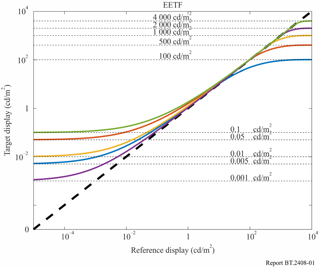
FIGURE 1 — Example EETF from 0 – 10 000 cd/m2 to various target displays
图 1. 从 0—10 000 cd/m² 映射到各类目标显示设备的 EETF 示例。
Annex 5 gives the specific mathematical steps to implement this tone mapping function for displays of various black and white luminance levels. Figure 2 shows the block diagram of where the EETF should be applied.
附件 5 给出了针对各种黑、白亮度电平的显示设备实现这一色调映射函数的具体数学步骤。图 2 以框图形式显示了 EETF 应施加的位置。
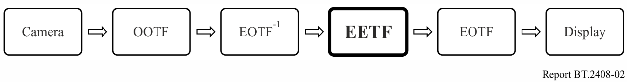
FIGURE 2 — Block diagram of signal chain showing location of EETF application
图 2. 信号链框图,显示 EETF 的施加位置。
3.2 Display of HLG signals
3.2 HLG 信号的显示
Table 5 of Recommendation ITU-R BT.2100 specifies the HLG EOTF (electro-optical transfer function) for reference displays. Note 5f specifies how the display’s gamma is adjusted to compensate for changes in the response of the human visual system as the eye adapts, when using HLG displays of different peak luminance. The gamma adjustment allows consistent signals to be produced from a range of displays with different peak luminance. Details can be found in § 6.2 of Report ITU-R BT.2390.
建议书 ITU-R BT.2100 表 5 规定了参考显示设备的 HLG EOTF(电光转换函数)。其注 5f 规定,在使用峰值亮度不同的 HLG 显示设备时,如何调整显示设备的伽马,以补偿眼睛适应过程中人眼视觉系统响应的变化。这一伽马调整使得各种不同峰值亮度的显示设备都能产生一致的信号。详见报告 ITU-R BT.2390 第 6.2 节。
The luminance on a production monitor corresponding to nominal peak, 100%, signal level, should be adjusted to a comfortable level for the viewing environment. Nominal peak signal level does not have to be set to the peak luminance of the monitor, which may be too bright for comfortable viewing. The nominal peak luminance of 1 000 cd/m2, identified in Recommendation ITU-R BT.2100, has been found to work well in typical production environments.
制作监视器上对应标称峰值(100%)信号电平的亮度,应针对观看环境调到舒适的水平。标称峰值信号电平不必设到监视器的峰值亮度,那可能亮得让人看着不舒服。实践发现,建议书 ITU-R BT.2100 所指出的 1 000 cd/m² 标称峰值亮度,在典型制作环境中效果良好。
Note 5g of Recommendation ITU-R BT.2100 recognises that the display’s gamma should further be adjusted to compensate for the adaptation state of the eye in non-reference production environments. A formula specifying the gamma adjustment is also given in § 6.2 of Report ITU-R BT.2390.
建议书 ITU-R BT.2100 注 5g 认识到,在非参考制作环境中,还应进一步调整显示设备的伽马,以补偿眼睛的适应状态。规定该伽马调整的公式同样见报告 ITU-R BT.2390 第 6.2 节。
Contrast, brightness and display system gamma (α, β and γ in Table 5 of Recommendation ITU-R BT.2100) are adjusted according to the viewing environment and nominal peak luminance of the display, as appropriate.
对比度、亮度和显示系统伽马(即建议书 ITU-R BT.2100 表 5 中的 α、β、γ),应酌情根据观看环境和显示设备的标称峰值亮度来调整。
Firstly, the monitor gamma is adjusted, according to the formula in Note 5f of Recommendation ITU-R BT.2100, to the appropriate value for the target nominal peak luminance of the display. The target nominal peak luminance may depend on the viewing environment.
首先,按建议书 ITU-R BT.2100 注 5f 的公式,把监视器伽马调到适合显示设备目标标称峰值亮度的取值。目标标称峰值亮度可能取决于观看环境。
Table 3 shows the gamma values for a range of typical production monitors in the reference viewing environment (5 cd/m2 surround).
表 3 给出参考观看环境(周边 5 cd/m²)下一系列典型制作监视器的伽马值。
表 3. HLG 显示伽马
| 标称峰值亮度(cd/m²) | 显示伽马 |
|---|---|
| 400 | 1.03 |
| 600 | 1.11 |
| 800 | 1.16 |
| 1 000 | 1.20 |
| 1 500 | 1.27 |
| 2 000 | 1.33 |
The display’s nominal peak luminance is then adjusted using the user gain control (legacy ‘contrast’ control) and a photometer, with an HDR reference white (75%HLG) window test patch (typically 1% screen area). Table 4 shows the luminance levels for a range of typical production monitors.
然后,借助用户增益控制(传统的“对比度”控制)和一台光度计,用 HDR 参考白(75%HLG)窗口测试色块(通常占屏幕面积的 1%)来调整显示设备的标称峰值亮度。表 4 给出一系列典型制作监视器的亮度电平。
表 4. 不同标称峰值显示设备的测试色块亮度电平
| 标称峰值亮度(cd/m²) | HDR 参考白(cd/m²) |
|---|---|
| 400 | 101 |
| 600 | 138 |
| 800 | 172 |
| 1 000 | 203 |
| 1 500 | 276 |
| 2 000 | 343 |
In non-reference viewing environments, a further adjustment should be made to the display’s system gamma to compensate for the adaptation state of the eye. Table 5 illustrates the recommended gamma adjustments for a range of common production environments, assuming a surround reflectance of approximately 60%, typical of light-coloured walls. However, for the greatest signal consistency, the reference conditions specified in Recommendation ITU-R BT.2100 should be used.
在非参考观看环境中,还应进一步调整显示设备的系统伽马,以补偿眼睛的适应状态。表 5 列出一系列常见制作环境的推荐伽马调整量,假定周边反射率约为 60%(浅色墙面的典型值)。不过,为求信号最大限度的一致,应采用建议书 ITU-R BT.2100 规定的参考条件。
表 5. 不同周边条件下的典型制作环境
| 典型环境 | 典型照度(勒克斯)(注 1) | 典型亮度(cd/m²)(注 2) | 典型伽马调整量 |
|---|---|---|---|
| 办公场所制作,晴天 | 130 | 25 | −0.05 |
| 办公场所制作,阴天 | 75 | 15 | −0.04 |
| 剪辑室 | 50 | 10 | −0.02 |
| 调色室 | 25 | 5 | 0.00 |
| 制作机房/暗调色室 | 3 | 0.5 | +0.08 |
NOTE 1: Measured perpendicular to the screen.
NOTE 2: Assuming ~ 60% reflectance surround.
注 1:垂直于屏幕方向测量。
注 2:假定周边反射率约为 60%。
As a guide, a gamma adjustment of 0.03 is just visible to the expert viewer when viewed side-by-side. Thus, no additional gamma adjustment is necessary across the majority of critical television production environments.
作为参考,0.03 的伽马调整量在并排比较时,专家观众刚好能看出来。因此,在大多数关键电视制作环境中无须额外的伽马调整。
However, a gamma adjustment is for bright environments such as those sometimes used for news production, or where a colourist prefers to work in a very dark environment.
不过,对于较亮的环境(如新闻制作有时所用的环境),或调色师偏好在极暗环境中工作的情形,则需要作伽马调整。
Lastly, the display black level is adjusted using the black level lift control (legacy ‘brightness’ control) and the Recommendation ITU-R BT.814 PLUGE signal, such that the negative stripes on the test pattern disappear, whilst the positive stripes remain visible.
最后,用黑位抬升控制(传统的“亮度”控制)和建议书 ITU-R BT.814 的 PLUGE 信号来调整显示设备的黑位,使测试图案上的负向条纹消失,而正向条纹仍可见。
3.2.1 Display of HLG signals on SDR screens
3.2.1 在 SDR 屏幕上显示 HLG 信号
For best results when displaying HLG signals on SDR screens, the SDR monitor should support the Recommendation ITU-R BT.2020 (BT.2020) colour gamut. However, for simple confirmation of the presence or absence of a signal, BT.709 colour monitoring may be sufficient. However, BT.709 colour monitors will show a de-saturated image with visible hue shifts.
要在 SDR 屏幕上显示 HLG 信号取得最佳效果,SDR 监视器应支持建议书 ITU-R BT.2020(下称 BT.2020)色域。不过,若只是简单确认有无信号,用 BT.709 色彩监看或许就够了;只是 BT.709 色彩监视器会显示出饱和度下降、并有明显色相偏移的图像。
Non-critical production monitors, such as multi-view production monitors, may be SDR BT.709 displays. A three-dimensional look-up table (3D-LUT) may be included in the monitoring chain to down-convert from BT.2100 HDR signals to BT.709 SDR, minimising colour distortions on such displays. Suitable look-up tables are often included within the display monitors themselves.
非关键制作监视器(如多画面制作监视器)可以是 SDR BT.709 显示设备。监看链路中可加入三维查找表(3D-LUT),把 BT.2100 HDR 信号下变换为 BT.709 SDR,从而尽量减小这类显示设备上的色彩失真。合适的查找表往往就内置于监视器自身之中。
4 Image brightness
4 图像亮度
Work has commenced on developing automatic objective measures for brightness, akin to those in common use for audio loudness today. Experimental results [2] show that a simple mean of displayed pixel luminances provides a good correlation with subjective brightness at 3.2 picture heights from the screen. The effectiveness of this simple objective metric suggests that real-time brightness monitoring in production is a realistic goal. This would give guidance to content producers, enabling comfortable viewing in the home, whilst allowing a range for artistic freedom. The metric could be used further to characterise long-term and short-term average brightness.
人们已着手研究亮度的自动客观度量,类似于今天音频响度领域常用的那种度量。实验结果 [2] 表明,在距屏幕 3.2 倍画面高度处观看时,所显示像素亮度的简单均值与主观亮度有良好的相关性。这一简单客观度量行之有效,说明在制作中进行实时亮度监测是一个现实可行的目标。它能为内容制作者提供指导,既保证家中观看的舒适,又为艺术自由留出空间。该度量还可进一步用来刻画长时与短时的平均亮度。
4.1 Comfortable brightness of static images
4.1 静态图像的舒适亮度
A study was performed by NHK to learn what range of luminances are judged comfortable by viewers. A number of SDR images that, on a 100 cd/m2 reference monitor, varied in average luminance over a range of 10-50 cd/m2, were used. The study was conducted using a relative display system that employed a 3 500 cd/m2 display that was adjusted to simulate a range of display luminance levels, thus the results are relevant to the HLG system that also employs displays with relative luminance. Peak luminances of 500, 1 000, 2 000, and 2 500 cd/m2 were simulated. Viewers were asked to judge whether images were ‘appropriate’, ‘too bright’, or ‘too dark’.
NHK 做了一项研究,以了解哪一段亮度范围会被观众判为舒适。研究使用了一批 SDR 图像,它们在 100 cd/m² 参考监视器上的平均亮度在 10—50 cd/m² 范围内变化。研究采用相对显示系统,用一台 3 500 cd/m² 显示设备经调整来模拟一系列显示亮度电平,因此结果同样适用于使用相对亮度显示设备的 HLG 系统。所模拟的峰值亮度为 500、1 000、2 000 和 2 500 cd/m²。观众被要求判断图像是“合适”“太亮”还是“太暗”。
Figure 3 shows the results in the reference viewing environment (dim surround). For each simulated display peak luminance, images with average luminance less than 25% of the peak luminance being simulated were not judged as ‘too bright’. Images with average luminance greater than 25% of peak luminance began to be judged as ‘too bright’ by many viewers. The judgements were essentially independent of the peak luminance being simulated on the display; this indicates that viewers’ eyes were adapting to the different display luminances. The implication of these results is that HLG images with average luminance of less than 250 cd/m2 on a 1 000 cd/m2 HLG monitor, would not be judged as too bright on an HLG monitor of any luminance up to at least 2 500 cd/m2.
图 3 给出参考观看环境(昏暗周边)下的结果。对每一个所模拟的显示峰值亮度,平均亮度低于所模拟峰值亮度 25% 的图像都未被判为“太亮”;平均亮度高于峰值亮度 25% 的图像,则开始被许多观众判为“太亮”。这些判断基本上与显示设备所模拟的峰值亮度无关,表明观众的眼睛在适应不同的显示亮度。这一结果意味着:在 1 000 cd/m² HLG 监视器上平均亮度低于 250 cd/m² 的 HLG 图像,在峰值亮度至少高达 2 500 cd/m² 的任何 HLG 监视器上都不会被判为太亮。
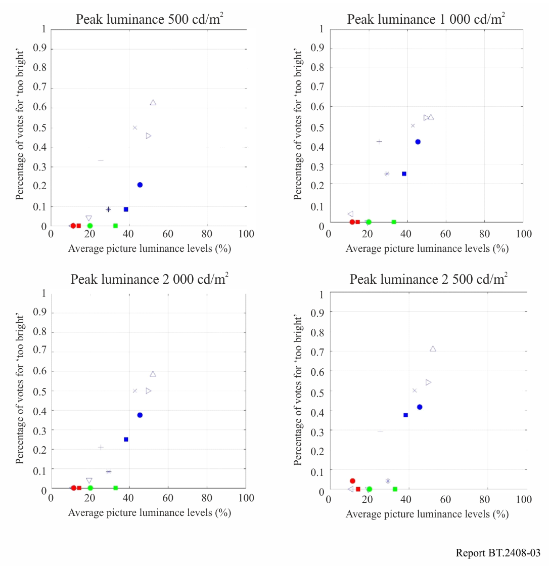
FIGURE 3 — Percentage of votes for ‘too bright’ in the reference environment (dim surround)
图 3. 参考环境(昏暗周边)下投票“太亮”的百分比。
This is consistent with informal comments from subjects in separate tests performed by the BBC, which were targeted at measuring tolerance to brightness jumps (see § 4.2). Having seen HDR video sequences on HLG displays with peak luminance levels of 1 000 cd/m2 and 4 000 cd/m2, 25% of subjects commented informally that the brightest scenes were uncomfortably bright regardless of any jumps. These scenes had average luminance levels of 268 and 363 cd/m2 on a 1 000 cd/m2 display. Similar comments were not made about the test scenes that had average luminances of 144 and 128 cd/m2 on a 1 000 cd/m2 display.
这与 BBC 另行开展、旨在测量观众对亮度跳变容忍度(见 4.2 节)的测试中受试者的非正式反馈相一致。在峰值亮度为 1 000 cd/m² 和 4 000 cd/m² 的 HLG 显示设备上看过 HDR 视频片段后,25% 的受试者非正式地反映,无论有无跳变,最亮的场景都亮得令人不适。这些场景在 1 000 cd/m² 显示设备上的平均亮度为 268 和 363 cd/m²。而对在 1 000 cd/m² 显示设备上平均亮度为 144 和 128 cd/m² 的测试场景,受试者则没有类似的反映。
Even when the static levels would be acceptable, sudden changes in brightness can be uncomfortable even when the static levels would be acceptable, so different requirements are needed to ensure viewer comfort when brightness jumps can occur.
即便静态电平本身可以接受,亮度的骤变仍可能让人不适,因此当可能发生亮度跳变时,需要另立要求来确保观众的舒适。
4.2 Tolerance to programme brightness shifts
4.2 对节目亮度跳变的容忍度
Unexpected changes in image brightness might occur between programmes, for example with interstitials. It is important to ensure that the brightness variations within HDR programmes are constrained to avoid viewer discomfort.
节目之间可能出现意料之外的图像亮度变化,例如插播垫片。务必确保 HDR 节目内部的亮度变化受到约束,以免引起观众不适。
Subjective tests reported by the BBC investigated viewer tolerance to sudden changes in overall brightness for HDR television, using the mean pixel display luminance as a measure of brightness as described in [2]. This measure has been shown to correlate well with subjective ratings of the overall brightness, but there may occasionally be a scene with a non-homogeneous spatial luminance distribution where the measure does not fully correspond to subjective brightness. For the tests, the luminance behind the screen was 5 cd/m2, and the peak screen luminance was 1 000 cd/m2 [3]. Subjects were asked to rate the change in overall brightness between two still HDR images.
BBC 报告的主观测试考察了观众对 HDR 电视整体亮度骤变的容忍度,采用文献 [2] 所述的像素显示亮度均值作为亮度度量。该度量已被证明与整体亮度的主观评分有良好相关性,但偶尔会有空间亮度分布不均的场景,使该度量与主观亮度不完全吻合。测试中,屏幕后方的亮度为 5 cd/m²,屏幕峰值亮度为 1 000 cd/m² [3]。受试者被要求对两幅 HDR 静态图像之间整体亮度的变化作出评分。
Figure 4 shows the overall results, with transitions from the first mean luminance A to the second mean luminance B categorised according to whether they are ‘not annoying’, ‘slightly annoying’, or ‘annoying’. Two regions are marked in the Figure with thick blue lines. The inner region, with mean display luminance levels of 5 to 80 cd/m2, contains only one possible ‘slightly annoying’ jump, and so could be considered a suitable range for operation that will not cause viewer discomfort. The outer region, with mean display luminance levels up to 160 cd/m2, includes several slightly annoying jumps, and so could be considered an extended range for creative effect. Further experiments reported by the BBC show that this outer region can be extended down to 2.5 cd/m2, and production trials with a prototype meter suggest that this extended range is appropriate.
图 4 给出总体结果,把从第一个平均亮度 A 跳变到第二个平均亮度 B 的情形,按“不恼人”“略恼人”“恼人”加以归类。图中用粗蓝线标出两个区域。内区的平均显示亮度电平为 5 至 80 cd/m²,其中只有一个可能“略恼人”的跳变,因此可视为不会引起观众不适的合适运行范围。外区的平均显示亮度电平最高达 160 cd/m²,含有若干略恼人的跳变,因此可视为追求创作效果的扩展范围。BBC 报告的进一步实验表明,该外区可向下扩展到 2.5 cd/m²,而用度量仪原型所做的制作试验显示,这一扩展范围是合适的。
Specific delivery requirements for luminance ranges are left to individual service providers, depending on their requirements. An example of requirement could be that the ranges can be freely exceeded over a short timescale, but the mean luminance over the length of a programme is kept within an operating range of 5 to 80 cd/m2. It should be noted that this range still allows for significant differences in brightness between programmes, so, for example, a ‘moody’ or ‘bright’ look can be achieved overall.
亮度范围的具体交付要求,由各服务提供方视自身需要自行决定。一个可能的要求示例是:短时间内可自由超出这些范围,但整档节目的平均亮度须保持在 5 至 80 cd/m² 的运行范围内。需要注意,这一范围仍允许节目之间存在显著的亮度差异,因此整体上仍可营造出“阴郁”或“明亮”的观感。
The results presented previously in Fig. 3 provide evidence that the eye adapts to a particular luminance level. Hence the scene-light levels corresponding to specified brightness shift tolerances are likely to be broadly applicable for HLG displays over a range of different peak luminances. This is supported by experiments reported by the BBC, which suggest that the ranges are applicable for HLG displays up to a peak luminance of 4 000 cd/m2.
前面图 3 的结果表明,眼睛会适应某一特定的亮度电平。因此,与给定亮度跳变容忍度相对应的场景光电平,很可能对一系列不同峰值亮度的 HLG 显示设备普遍适用。BBC 报告的实验支持这一点,其结果表明这些范围对峰值亮度高达 4 000 cd/m² 的 HLG 显示设备都适用。
It should be noted that shadow detail may be lost after a transition from a bright scene to a very dark scene, even if the transition is not uncomfortable, because it takes time for the eyes to adapt. Also, a comfortable overall brightness does not ensure that the content makes good use of the available dynamic range. Further guidance may be useful to characterise best use of the dynamic range for common scene types.
需要注意,从明亮场景切到非常暗的场景后,即便切换本身并不令人不适,暗部细节也可能丢失,因为眼睛需要时间来适应。此外,整体亮度舒适并不能保证内容充分利用了可用的动态范围。对常见场景类型如何最好地利用动态范围,进一步的指导可能会有帮助。
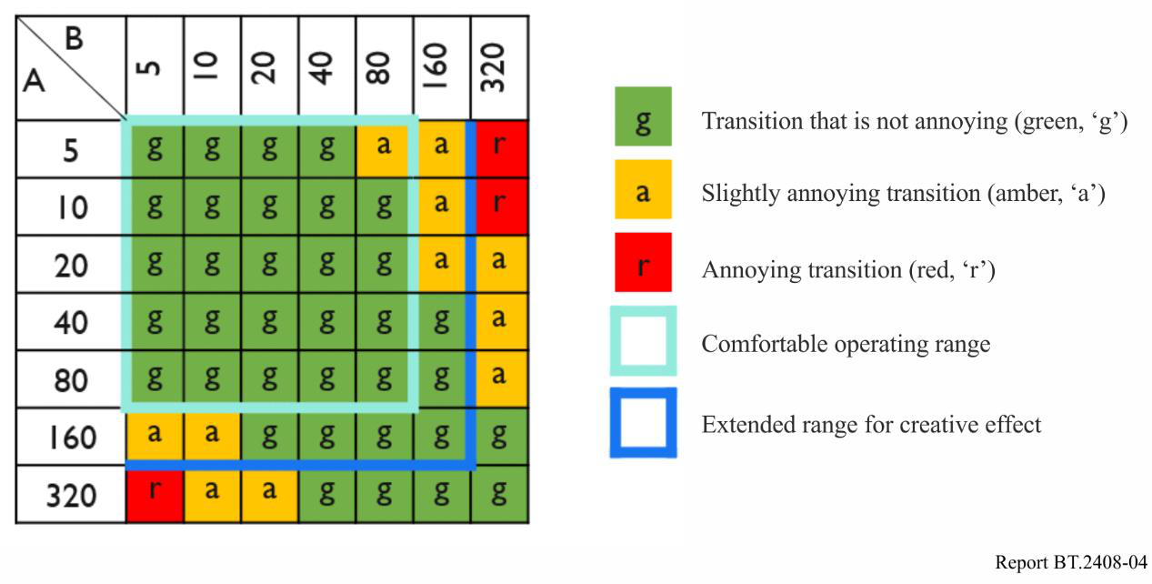
FIGURE 4 — Transitions from mean luminance A (cd/m2) to mean luminance B (cd/m2) categorised by level of annoyance
图 4. 从平均亮度 A(cd/m²)跳变到平均亮度 B(cd/m²),按恼人程度分类。
5 Integrating standard dynamic range and high dynamic range production
5 标准动态范围与高动态范围制作的融合
Definitions
定义
Tone Mapping (TM) – Compression of the image dynamic range of content. It may be used to ‘down-map’ (down-convert) HDR content to SDR content.
色调映射(TM)——压缩内容的图像动态范围。可用于把 HDR 内容“下映射”(下变换)为 SDR 内容。
Inverse Tone Mapping (ITM) – Expansion of the image dynamic range of content. It may be used to ‘up-map’ (up-convert) SDR content to emulate the appearance of HDR content. Also referred to as ‘up-mapping’.
逆色调映射(ITM)——扩展内容的图像动态范围。可用于把 SDR 内容“上映射”(上变换)以模拟 HDR 内容的观感,也称“上映射”。
Direct-mapping – In the context of converting SDR content to HDR content, Direct-mapping is intended to preserve the appearance of the SDR content so that the HDR version displayed on a reference HDR monitor will look similar to the original SDR version displayed on a reference SDR display. A luminance gain (e.g. 2x) and other processing will provide a better match to the luminance of a native HDR image while maintaining the SDR appearance.
直接映射——在把 SDR 内容转换为 HDR 内容的语境中,直接映射意在保留 SDR 内容的观感,使在参考 HDR 监视器上显示的 HDR 版本,看上去与在参考 SDR 显示设备上显示的原始 SDR 版本相近。施加亮度增益(如 2 倍)及其他处理,可在保持 SDR 观感的同时,更好地匹配原生 HDR 图像的亮度。
Hard Clipping – When converting from HDR to SDR there are some circumstances when hard clipping rather than tone mapping (akin to soft clipping) may be more appropriate. With hard clipping all signals above a threshold are clipped to that threshold. Hard clipping is useful when the signal from an HDR camera is required to look similar to the signal delivered by an SDR camera operated without a ‘knee’.
硬削波——从 HDR 转换为 SDR 时,某些情形下硬削波比色调映射(类似软削波)更合适。硬削波会把所有高于某阈值的信号都削到该阈值。当要求 HDR 相机的信号看起来与不带“拐点”的 SDR 相机所输出的信号相近时,硬削波就很有用。
Artistic Intent – A creative choice that the programme maker would like to preserve, primarily conveyed through the use of colour and tone.
艺术意图——节目制作者希望保留的创作选择,主要通过色彩和色调来传达。
Look – A characteristic of the displayed image. The native appearance of colours and tones of a particular system (for example, PQ, HLG, BT.709) as seen by the viewer.
观感(look)——所显示图像的一种特征,即某一特定系统(如 PQ、HLG、BT.709)的色彩和色调被观众看到时的原生外观。
5.1 Inclusion of standard dynamic range content in high dynamic range
5.1 在高动态范围制作中纳入标准动态范围内容
SDR content may either be direct-mapped or inverse tone mapped (up-mapped) into an HDR format for inclusion in HDR programmes. Direct-mapping places SDR content into an HDR container, analogously to how content specified using BT.709 colorimetry may be placed in a BT.2020 container. This approach is intended to preserve the appearance of the SDR content when shown on an HDR display. In contrast, inverse tone mapping (up-mapping) is intended to expand the content to use more of the available HDR luminance range and thereby leverage more of the display capabilities. Up-mapping is intended to make content captured in SDR look more as if it had been captured in HDR even though the highlights are more limited.
要把 SDR 内容纳入 HDR 节目,可对其进行直接映射,也可进行逆色调映射(上映射)以转入 HDR 格式。直接映射是把 SDR 内容装入 HDR 容器,类似于把按 BT.709 色度学制作的内容装入 BT.2020 容器。这种做法意在让 SDR 内容在 HDR 显示设备上呈现时保留原有观感。相比之下,逆色调映射(上映射)则意在扩展内容,使其用上更多可用的 HDR 亮度范围,从而更充分地发挥显示设备的能力。上映射意在让以 SDR 采集的内容看上去更像是以 HDR 采集的,尽管其高光仍较为有限。
There are two possible approaches to both SDR direct-mapping and up-mapping depending on the application:
无论是 SDR 直接映射还是上映射,都有两种可能的做法,视应用而定:
– Display-referred mapping is used when the goal is to preserve the colours and relative tones seen on an SDR display, when the content is shown on an HDR display; an example of which is the inclusion of SDR graded content within an HDR programme. Display-referred mappings are derived by applying the desired EOTF (Recommendation ITU-R BT.1886), scaling the displayed light signal to match the brightness of HDR content. These are known as ‘display-light’ conversions.
- 显示参考映射:当目标是让内容在 HDR 显示设备上呈现时,保留它在 SDR 显示设备上所见的色彩和相对色调时,采用此法;例如把经 SDR 调色的内容纳入 HDR 节目。显示参考映射的导出方式是:施加所需的 EOTF(建议书 ITU-R BT.1886),再缩放显示光信号以匹配 HDR 内容的亮度。这类做法称为“显示光”转换。
– Scene-referred mapping is used when the goal is to match the colours and relative tones of a native HDR and native SDR camera; an example of which is the inter-mixing of SDR and HDR cameras within a live television production. Scene-referred mappings are based on the light falling on the camera sensor, but they include any camera characteristics, white balance, and any artistic camera adjustments. These are known as ‘scene-light’ conversions.
- 场景参考映射:当目标是匹配原生 HDR 相机与原生 SDR 相机的色彩和相对色调时,采用此法;例如在电视直播制作中把 SDR 与 HDR 相机混用。场景参考映射以落在相机传感器上的光为基础,但其中包含相机的各种特性、白平衡以及任何艺术性相机调整。这类做法称为“场景光”转换。
The nominal signal levels described in § 2.2 may be helpful to guide midtone levels during mapping.
2.2 节所述的标称信号电平,可在映射时帮助指导中间调的电平。
The following subsections describe several different methods for mapping SDR into HDR. The choice of mapping method depends on the application and should be made by implementers based on their needs and on the documented goals and characteristics of each method. Currently, there is no universal approach. The following guidance is provided.
以下各小节介绍把 SDR 映射到 HDR 的若干不同方法。映射方法的选择取决于应用,应由实现者根据自身需要、以及各方法所记载的目标和特性来决定。目前尚无通用方法,特提供以下指导。
5.1.1 Display referred mapping
5.1.1 显示参考映射
Figures 5 and 6 illustrate the display-referred mapping of SDR signals into either HLG or PQ.
图 5 和图 6 示意把 SDR 信号显示参考映射到 HLG 或 PQ。
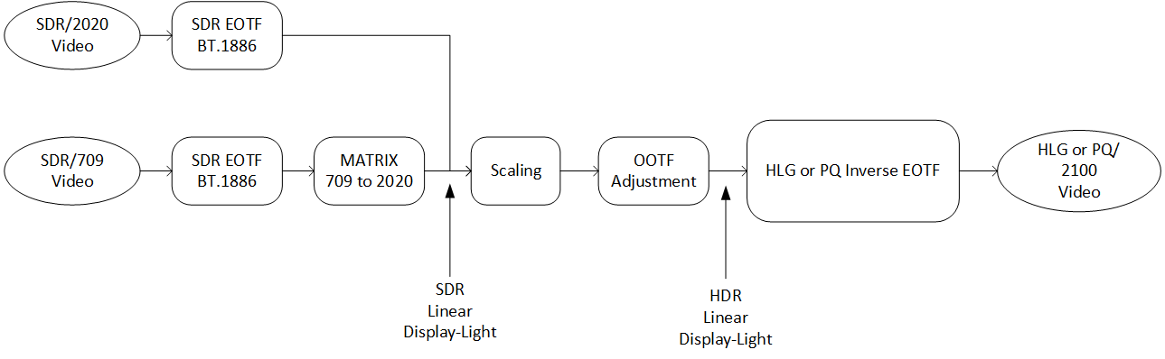
FIGURE 5 — Method with linear scaling for ‘display-referred’ mapping of SDR into HLG or PQ
图 5. 采用线性缩放、把 SDR“显示参考”映射到 HLG 或 PQ 的方法。
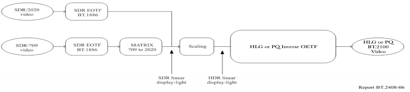
FIGURE 6 — Method with OOTF adjustment for ‘display-referred’ mapping of SDR into HLG or PQ
图 6. 采用 OOTF 调整、把 SDR“显示参考”映射到 HLG 或 PQ 的方法。
The SDR signal is first passed through the BT.1886 reference EOTF to derive SDR linear display light. An approximation of the electro-optical transfer function (EOTF) from Recommendation ITU-R BT.1886 may be used:
先让 SDR 信号通过 BT.1886 参考 EOTF,得出 SDR 线性显示光。可使用建议书 ITU-R BT.1886 电光转换函数(EOTF)的近似式:
where:
E′ is the non-linear signal (R′, G′, B′) in the range [0:1]
E is the normalised linear display light in the range [0:1].
式中:
- E′ 为非线性信号(R′、G′、B′),取值范围 [0, 1];
- E 为归一化的线性显示光,取值范围 [0, 1]。
A colour space conversion from BT.709 primaries to BT.2020/BT.2100 colour primaries is performed if necessary, details of which can be found in Recommendation ITU-R BT.2087.
如有必要,再作从 BT.709 基色到 BT.2020/BT.2100 基色的色彩空间转换,详见建议书 ITU-R BT.2087。
The linear SDR display light may then be scaled to ensure that 100% SDR maps to a similar level to HDR reference white of 203 cd/m2.
然后可对线性 SDR 显示光作缩放,确保 100% SDR 映射到与 203 cd/m² 的 HDR 参考白相近的电平。
Where scaling is performed,
进行缩放时:
• If the goal when direct-mapping into HDR is to mimic the appearance of SDR content displayed on a BT.1886 SDR display with peak luminance 203 cd/m2, or to minimize losses when SDR material is ‘round-tripped’ through a complementary ‘hybrid-linear’ down mapper described in Annex 10, a 2.03× linear scaling without OOTF (opto-optical transfer function) adjustment will produce the desired results (see § 5.1.2).
- 若直接映射到 HDR 的目标是模拟 SDR 内容在峰值亮度 203 cd/m² 的 BT.1886 SDR 显示设备上的观感,或是在 SDR 素材经附件 10 所述互补的“混合线性”下映射器“往返转换”时尽量减少损失,则采用 2.03× 的线性缩放、不作 OOTF(光光转换函数)调整,即可得到预期结果(见 5.1.2 节)。
• If the goal when direct-mapping into HDR is to maintain the subjective appearance of the 100 cd/m2 SDR original content, for example in the SDR focused-production workflow described in § 7.3, a small ‘gamma’ adjustment (or similar) to the OOTF should then be applied. The OOTF adjustment compensates for the subjective change in appearance of the SDR signal arising from a 2.03× linear scaling; thereby ensuring that the visibility of detail in the shadows and the appearance of skin tones in the 100 cd/m2 original are maintained (see § 5.1.3.2).
- 若直接映射到 HDR 的目标是保持 100 cd/m² SDR 原始内容的主观观感(例如 7.3 节所述以 SDR 为重心的制作工作流),则应对 OOTF 作一个小幅“伽马”调整(或类似处理)。该 OOTF 调整用来补偿 2.03× 线性缩放所引起的 SDR 信号主观观感变化,从而确保 100 cd/m² 原始内容中暗部细节的可见性和肤色的观感得以保持(见 5.1.3.2 节)。
Having scaled and adjusted the SDR display light, the resulting signal is passed through an HLG or PQ inverse EOTF to provide either an HLG or PQ signal.
对 SDR 显示光作缩放和调整后,让所得信号通过 HLG 或 PQ 逆 EOTF,即可得到 HLG 或 PQ 信号。
5.1.2 Display referred mapping of SDR into PQ
5.1.2 把 SDR 显示参考映射到 PQ
The following procedure may be followed to achieve consistent midtone luminance levels when mapping standard dynamic range content into PQ.
把标准动态范围内容映射到 PQ 时,可按以下步骤获得一致的中间调亮度电平。
Standard dynamic range BT.2020 content should be mapped to PQ by applying the BT.1886 display EOTF and then applying the PQ EOTF-1.
应先施加 BT.1886 显示 EOTF、再施加 PQ EOTF⁻¹,把标准动态范围 BT.2020 内容映射到 PQ。
V: Input SDR video signal level (normalized, black at V = 0, to white at V = 1)
LW: SDR screen luminance for white = 100 cd/m2
LB: Screen luminance for black = 0 cd/m2
E′: Output PQ video signal level (normalized [0:1])
Scaling: EOTFPQ (E′V=1) / 100 cd/m2
Example: for scaling = 2.03, E′V=1 = 0.58 and EOTFPQ (E′V=1) = 203 cd/m2
式中:
- V:输入 SDR 视频信号电平(归一化,黑为 V = 0,白为 V = 1);
- L_W:白的 SDR 屏幕亮度 = 100 cd/m²;
- L_B:黑的屏幕亮度 = 0 cd/m²;
- E′:输出 PQ 视频信号电平(归一化 [0, 1]);
- 缩放系数:EOTF_PQ(E′_{V=1}) / 100 cd/m²;
- 示例:当缩放系数 = 2.03 时,E′_{V=1} = 0.58,且 EOTF_PQ(E′_{V=1}) = 203 cd/m²。
A scaling factor of 2.03 is consistent with the HDR level guidance of § 2.2, as that will map the 100 cd/m2 nominal peak white level of SDR to approximately the 203 cd/m2 level for HDR or 58%PQ. However, such a linear scaling will not maintain the subjective appearance of the SDR content on an HDR display when the original is shown in a 100 cd/m2 BT.2035 environment, as it takes no account of the non-linear response of the eye. MovieLabs has found that linear scaling provides a good match to the way consumer displays scale SDR content in their ‘home cinema’ viewing modes [4] because it mimics the linear scaling in BT.1886. Linear scaling can typically provide a closer tonal match to the scene light up-/direct-mapper which may be a useful feature for mixed SDR/HDR where intercutting of the two sources might occur.
2.03 的缩放系数与 2.2 节的 HDR 电平指导一致,因为它会把 SDR 的 100 cd/m² 标称峰值白电平映射到约 203 cd/m² 的 HDR 电平、即 58%PQ。不过,当原始内容在 100 cd/m² 的 BT.2035 环境中显示时,这种线性缩放并不能保持 SDR 内容在 HDR 显示设备上的主观观感,因为它没有考虑眼睛的非线性响应。MovieLabs 发现,线性缩放与消费类显示设备在其“家庭影院”观看模式下缩放 SDR 内容的方式吻合良好 [4],因为它模仿了 BT.1886 中的线性缩放。线性缩放通常能与场景光上映射/直接映射器在色调上更贴近,这在 SDR/HDR 混合、两种源可能交替剪切的场合或许是个有用的特性。
The 2.03× linear scaling may also provide a good tonal match to HDR cameras that have not been ‘painted’ (see § 7.7), which can be important when including archive content in live (or as live) programming.
2.03× 的线性缩放还可能与未经“调校(painting)”的 HDR 相机(见 7.7 节)在色调上吻合良好,这在把存档内容纳入直播(或准直播)节目时可能很重要。
For standard dynamic range BT.709 content the same process may be used, with the BT.709 to BT.2020 conversion matrix applied before the scaling as shown in Fig. 5 and Fig. 6.
对标准动态范围 BT.709 内容,可使用同样的流程,只需如图 5 和图 6 所示,在缩放之前先施加 BT.709 到 BT.2020 的转换矩阵。
5.1.3 Display referred mapping of SDR into HLG
5.1.3 把 SDR 显示参考映射到 HLG
5.1.3.1 Mapping without OOTF adjustment
5.1.3.1 不作 OOTF 调整的映射
The ‘display-referred’ method of mapping SDR content into a Hybrid Log-Gamma (HLG) container, without an OOTF adjustment, is illustrated in Fig. 7.
把 SDR 内容映射进混合对数伽马(HLG)容器、不作 OOTF 调整的“显示参考”方法,见图 7。
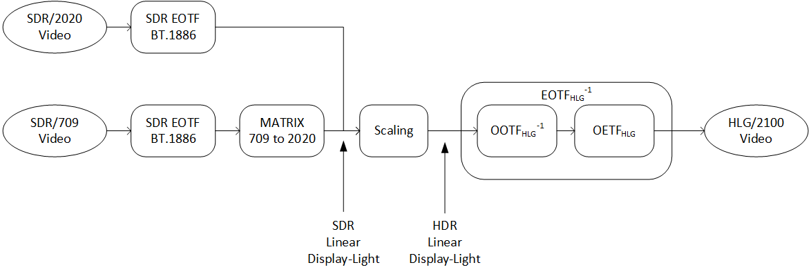
FIGURE 7 — SDR to HLG mapping without gamma adjustment (display-referred)
图 7. 不作伽马调整的 SDR 到 HLG 映射(显示参考)。
5.1.3.2 Mapping with OOTF adjustment
5.1.3.2 作 OOTF 调整的映射
For the case when an OOTF ‘gamma’ adjustment is made to the scaled SDR display light, the process is shown in Fig. 8.
对缩放后的 SDR 显示光作 OOTF“伽马”调整的情形,其流程见图 8。
To double the displayed nominal peak luminance of an SDR signal for direct-mapping into HLG, whilst maintaining the subjective appearance of viewing at 100 cd/m2, a compensating adjustment to the OOTF gamma can be used. Subjective tests carried out by the BBC and ARIB independently have found that an OOTF adjustment of 1.15-1.16 works well to preserve the appearance of shadows and midtones of the native SDR content at 100 cd/m2 while scaling the SDR nominal peak white to 203 cd/m2. Note that the OOTF gamma adjustment boosts the contrast (perceptible, but not annoying) especially when the native SDR content contains highlights and super-whites.
要在把 SDR 信号直接映射进 HLG 时,将其显示标称峰值亮度提高一倍,同时保持在 100 cd/m² 观看时的主观观感,可对 OOTF 伽马作一个补偿性调整。BBC 与 ARIB 各自独立开展的主观测试发现,1.15—1.16 的 OOTF 调整量,能在把 SDR 标称峰值白缩放到 203 cd/m² 的同时,很好地保留 100 cd/m² 原生 SDR 内容暗部和中间调的观感。需要注意,OOTF 伽马调整会提升对比度(可察觉,但不恼人),尤其当原生 SDR 内容含有高光和超白时。
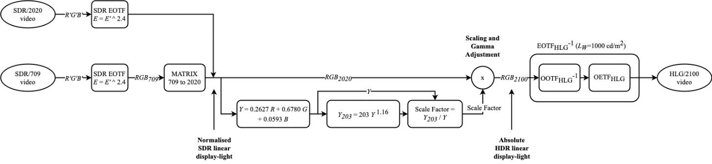
FIGURE 8 — Model for ‘display-referred’ mapping with OOTF ‘gamma’ adjustment of SDR into HLG
图 8. 带 OOTF“伽马”调整、把 SDR“显示参考”映射到 HLG 的模型。
Having scaled and adjusted the SDR display light, the resulting signal is passed through an HLG inverse EOTF to provide the HLG signal.
对 SDR 显示光作缩放和调整后,让所得信号通过 HLG 逆 EOTF,即可得到 HLG 信号。
5.1.3.3 Scaling
5.1.3.3 缩放
When (100X)%SDR signal is mapped to (100Y)%HLG signal, a scaling gain is calculated by the following equation:
当把 (100X)% 的 SDR 信号映射到 (100Y)% 的 HLG 信号时,缩放增益按下式计算:
For example, when 100% SDR signal is mapped to 75% HLG (203 cd/m2 on a 1 000 cd/m2 display), the scaling gain is calculated as follows:
例如,当把 100% 的 SDR 信号映射到 75% HLG(在 1 000 cd/m² 显示设备上为 203 cd/m²)时,缩放增益计算如下:
5.1.3.4 Simplification of the HLG mapping process
5.1.3.4 HLG 映射流程的简化
Through careful choice of the HLG inverse EOTF parameters, it is possible to avoid the need to scale and adjust the gamma of the SDR linear display light signal. By configuring the HLG inverse EOTF with a nominal peak luminance, LW, of 392 cd/m2, an input of 100 cd/m2 from the SDR EOTF will directly deliver an HLG signal of 75%, satisfying the requirement to map 100%SDR signal to 75%HLG signal, without further scaling and gamma adjustment.
通过精心选择 HLG 逆 EOTF 的参数,可以免去对 SDR 线性显示光信号作缩放和伽马调整的步骤。把 HLG 逆 EOTF 的标称峰值亮度 L_W 配置为 392 cd/m²,则来自 SDR EOTF 的 100 cd/m² 输入会直接产生 75% 的 HLG 信号,满足把 100% SDR 信号映射到 75% HLG 信号的要求,而无须再作缩放和伽马调整。
Figure 8 illustrates how, for all but the most critical applications, it is possible to simplify the conversion yet further. When applying the HLG inverse EOTF with LW set to 392 cd/m2, Note 5e of Recommendation ITU-R BT.2100 requires a gamma value of 1.03. As this is close to unity, in most applications there is no need to apply the inverse OOTF gamma to the luminance component, it can instead be applied independently to R, G and B components; greatly simplifying the mapping process. Colour distortions that usually arise through applying gamma to red, green and blue, rather than luminance, are barely visible for such low values of gamma.
图 8 说明,除最关键的应用外,转换还可进一步简化。当施加 L_W 设为 392 cd/m² 的 HLG 逆 EOTF 时,建议书 ITU-R BT.2100 注 5e 要求伽马值为 1.03。由于这接近 1,在大多数应用中无须对亮度分量施加逆 OOTF 伽马,而可改为对 R、G、B 各分量分别施加,从而大大简化映射流程。对红、绿、蓝(而非亮度)施加伽马通常会引起的色彩失真,在伽马值如此之低时几乎不可见。
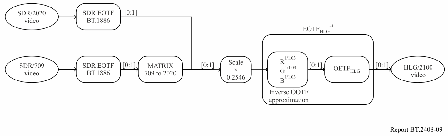
FIGURE 9 — Simplified (display-referred) SDR to mapping into HLG
图 9. 简化的(显示参考)SDR 到 HLG 映射。
As normalised signals are used throughout, a different scaling is required to match the signal ranges of the SDR EOTF and HDR inverse EOTF, thereby ensuring that 100%SDR signal maps to 75% of the HLG HDR signal. Note that as the normalised signals are dimensionless, the scaler is not adjusting the peak luminance of the SDR display light, so no additional gamma compensation for the signal scaling is required. Allowing for the inverse OOTF gamma of 1.03, the correct scale factor is 0.2546.
由于全程使用归一化信号,需要一个不同的缩放系数来匹配 SDR EOTF 与 HDR 逆 EOTF 的信号范围,从而确保 100% SDR 信号映射到 75% 的 HLG HDR 信号。需要注意,归一化信号是无量纲的,缩放器并未调整 SDR 显示光的峰值亮度,因此无须为信号缩放再作额外的伽马补偿。计入 1.03 的逆 OOTF 伽马后,正确的缩放系数为 0.2546。
5.1.4 Scene referred mapping
5.1.4 场景参考映射
It is particularly important that the scene-referred mapping is used for matching signals from BT.709 and BT.2020 SDR cameras with signals from HLG cameras. This is because, direct from the camera (and prior to subjective adjustment), both signals represent light from the scene captured by the camera.
要让 BT.709 和 BT.2020 SDR 相机的信号与 HLG 相机的信号相匹配,使用场景参考映射尤为重要。这是因为,直接来自相机(且在作主观调整之前)的两路信号,都代表相机所采集的场景光。
If the display-referred mapping were used, which maintains the appearance of SDR images on an HLG display, the signals from SDR cameras and HLG cameras would not match. This is because the displayed ‘look’ of SDR and HLG images, from cameras that implement the reference OETFs (opto-electronic transfer functions), is different (see § 7.6.3 and Annex 6).
若改用显示参考映射(它保持 SDR 图像在 HLG 显示设备上的观感),则 SDR 相机与 HLG 相机的信号将无法匹配。这是因为,对实现了参考 OETF(光电转换函数)的相机而言,SDR 与 HLG 图像所显示的“观感”是不同的(见 7.6.3 节和附件 6)。
Scene-referred mapping will also work for mapping SDR to PQ. However, because the ‘look’ of PQ and BT.2020 SDR signals is very similar, for BT.2020 SDR signals the display-referred mapping will generally work well. To best match the PQ ‘look’, BT.709 SDR camera signals could be converted to BT.2020 SDR camera signals (using an OETF-based conversion similar to that specified in Recommendation ITU-R BT.2087) before display-referred mapping is applied.
场景参考映射也适用于把 SDR 映射到 PQ。不过,由于 PQ 与 BT.2020 SDR 信号的“观感”非常相似,对 BT.2020 SDR 信号而言,显示参考映射通常就效果良好。为最大限度匹配 PQ 的“观感”,可在施加显示参考映射之前,先把 BT.709 SDR 相机信号转换为 BT.2020 SDR 相机信号(采用类似建议书 ITU-R BT.2087 所规定的、基于 OETF 的转换)。
The schematic diagram of the scene-referred mapping is illustrated in Fig. 10 for both PQ and HLG. It includes an optional artistic OOTF adjustment, for example to match the ‘traditional colour reproduction’ described in § 6.5 of Report ITU-R BT.2390.
场景参考映射针对 PQ 和 HLG 的原理框图见图 10。其中包含一个可选的艺术 OOTF 调整,例如用以匹配报告 ITU-R BT.2390 第 6.5 节所述的“传统色彩还原”。
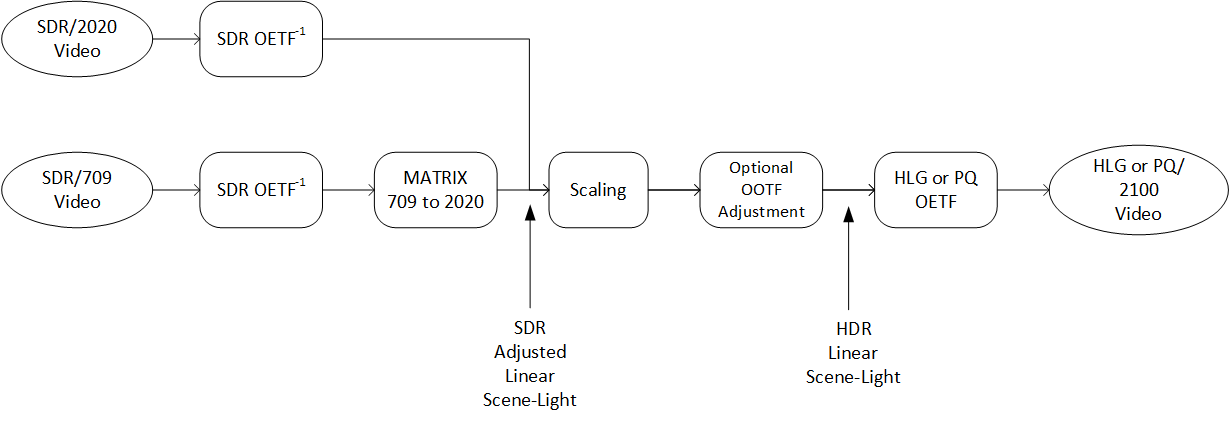
FIGURE 10 — SDR to HDR mapping (scene-referred)
图 10. SDR 到 HDR 映射(场景参考)。
Figure 10 shows how the non-linear SDR BT.709 or BT.2020 video signal is converted to linear ‘scene light’ by applying the approximate inverse of SDR OETF, 𝐸=(𝐸′)2, as described in BT.2087. When the SDR source is with the BT.709 colorimetry, the conversion is followed by the colour conversion matrix as described in Recommendation ITU-R BT.2087.
图 10 显示如何按 BT.2087 所述,施加 SDR OETF 的近似逆 E = (E′)² ,把非线性的 SDR BT.709 或 BT.2020 视频信号转换为线性的“场景光”。当 SDR 源采用 BT.709 色度学时,转换之后再按建议书 ITU-R BT.2087 所述施加色彩转换矩阵。
The scene light signal is then scaled so that the non-linear signal, after applying the reference PQ or HLG OETF, is at the appropriate signal level for HDR reference white: 58% PQ or 75%HLG respectively. Following any OOTF adjustment, the HLG or PQ OETFs are applied to derive the non-linear signals.
然后对场景光信号作缩放,使其在施加参考 PQ 或 HLG OETF 之后,所得非线性信号恰好处于 HDR 参考白的合适信号电平:分别为 58% PQ 或 75% HLG。在作任何 OOTF 调整之后,再施加 HLG 或 PQ OETF,得出非线性信号。
Section 5.1.4.1 describes how to calculate the scale factor for HLG, as well as how to adjust the OOTF to preserve a traditional SDR look.
第 5.1.4.1 节说明如何计算 HLG 的缩放系数,以及如何调整 OOTF 以保留传统的 SDR 观感。
5.1.4.1 Scene referred mapping of SDR into HLG
5.1.4.1 把 SDR 场景参考映射到 HLG
When (100X)%SDR signal is mapped to (100Y)%HLG signal, a scaling gain is calculated by the following equation:
当把 (100X)% 的 SDR 信号映射到 (100Y)% 的 HLG 信号时,缩放增益按下式计算:
For example, when 100%SDR signal is mapped to 75%HLG signal, the scaling gain is calculated as follows:
例如,当把 100% 的 SDR 信号映射到 75% 的 HLG 信号时,缩放增益计算如下:
Where the SDR ‘look’ is maintained during the conversion from SDR to HDR or the HLG camera is designed to deliver a traditional ‘look’ (see § 6.5 of Report ITU-R BT.2390), a small optional adjustment to the OOTF may then be applied to compensate for the subjective change in appearance of the SDR signal arising from a difference between HLG and SDR OOTFs. For the case when gamma adjustment is made to the scaled SDR scene light, the process is illustrated in Fig. 11.
当在 SDR 到 HDR 的转换中要保持 SDR 的“观感”,或 HLG 相机被设计为产生传统“观感”(见报告 ITU-R BT.2390 第 6.5 节)时,可对 OOTF 作一个小幅的可选调整,以补偿 HLG 与 SDR OOTF 之间差异所引起的 SDR 信号主观观感变化。对缩放后的 SDR 场景光作伽马调整的情形,其流程见图 11。
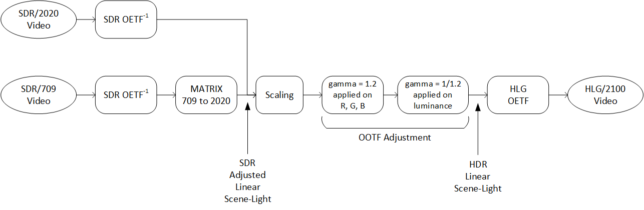
FIGURE 11 — SDR to HLG mapping with gamma adjustment (scene-referred)
图 11. 带伽马调整的 SDR 到 HLG 映射(场景参考)。
5.1.5 Comparing scene-light and display-light direct-mapping
5.1.5 场景光直接映射与显示光直接映射的比较
The difference in the tonal responses of scene-light direct-mapping (which takes no account of the changed in displayed luminance between SDR and HDR) and display-light direct-mapping with a compensating OOTF adjustment, is illustrated in Fig. 12. The colour differences between the two approaches are discussed in § 7.6.3.
场景光直接映射(不考虑 SDR 与 HDR 之间显示亮度的变化)与带补偿性 OOTF 调整的显示光直接映射,二者色调响应的差异见图 12。两种做法之间的色差在 7.6.3 节讨论。
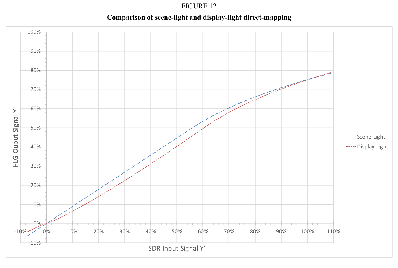
FIGURE 12 — Comparison of scene-light and display-light direct-mapping
图 12. 场景光直接映射与显示光直接映射的比较。
The Figure shows how the midtones are brighter in the scene-light conversion than in the display-light conversion. It is only the display-light conversion that aims to preserve the subjective appearance of the SDR signal shown on a Recommendation ITU-R BT.2035 100 cd/m2 reference display.
该图显示,场景光转换的中间调比显示光转换更亮。只有显示光转换才以保留 SDR 信号在建议书 ITU-R BT.2035 的 100 cd/m² 参考显示设备上所呈现的主观观感为目标。
5.2 HDR to SDR down-mapping
5.2 HDR 到 SDR 的下映射
As with SDR to HDR conversion, HDR to SDR down-mapping can be performed using either scene-light or display-light. Scene-light conversions match the appearance of SDR cameras, but are no longer widely used for down-mapping as they change the appearance in both colour and tone of embedded graphics. Display-light down-mapping attempts to maintain the ‘look’ of the HDR source when converted to SDR, and is usually preferred.
与 SDR 到 HDR 的转换一样,HDR 到 SDR 的下映射也可用场景光或显示光来完成。场景光转换能匹配 SDR 相机的观感,但因其会改变嵌入图形在色彩和色调上的观感,如今已不再广泛用于下映射。显示光下映射力求在转换为 SDR 时保持 HDR 源的“观感”,通常更受青睐。
Report ITU-R BT.2446 describes three example methods of display-light HDR to SDR conversion (and vice-versa). Each method attempts to preserve the subjective appearance of the lowlights and midtones in the HDR image, when the tone-mapped SDR is shown on a Recommendation ITU-R BT.2035 100 cd/m2 display.
报告 ITU-R BT.2446 描述了显示光 HDR 到 SDR 转换(及其逆向)的三种示例方法。当经色调映射的 SDR 在建议书 ITU-R BT.2035 的 100 cd/m² 显示设备上呈现时,每种方法都力求保留 HDR 图像中暗部和中间调的主观观感。
The HDR to SDR down-mapper used to monitor or shade the HDR signal in production should match the characteristics of the linear or non-linear down-mapper used to create the SDR version of the programme transmission output. Table 6 illustrates the effects that can occur when different down-mapping techniques are used.
制作中用于监看或对 HDR 信号作明暗控制的 HDR 到 SDR 下映射器,应与用于生成节目播出输出 SDR 版本的线性或非线性下映射器特性相匹配。表 6 列出采用不同下映射技术时可能出现的效果。
表 6. 摄像机明暗控制方法与由 HDR 下映射所得的 SDR
| 明暗控制方式 | HDR 分发 | SDR 分发:由 HDR 非线性下映射 | SDR 分发:由 HDR 线性下映射 |
|---|---|---|---|
| HDR 明暗控制,峰值亮度 1 000 cd/m²(BT.2100) | 符合预期 | 符合预期 | 中间调偏暗 |
| SDR 明暗控制,由 HDR 下映射至 100 cd/m²(BT.2035),非线性下映射器 | 符合预期 | 符合预期 | 中间调偏暗 |
| SDR 明暗控制,由 HDR 下映射至 100 cd/m²(BT.2035),线性下映射器 | 中间调偏亮 | 中间调偏亮 | 符合预期 |
A linear down-mapping (.5 scaling factor) will not preserve the subjective appearance of the HDR in the SDR image when viewed on a reference 100 cd/m2 SDR display. See Table A10-1 in Annex 10 for an illustration of how the linear down-mapper can be used with good effect under conditions described in BT.1886/BT.2129 where a typically higher SDR luminance level is used.
线性下映射(0.5 的缩放系数)在 100 cd/m² 参考 SDR 显示设备上观看时,无法保留 SDR 图像中 HDR 的主观观感。附件 10 的表 A10-1 举例说明,在 BT.1886/BT.2129 所述、通常采用较高 SDR 亮度电平的条件下,线性下映射器如何能取得良好效果。
Using a non-linear scaling for down-mapping, with an additional OOTF adjustment, often in the form of a gamma adjustment, can preserve the look of lowlights and midtones while providing a good roundtrip with a non-linear gamma-adjusted up/direct-mapping (see § 5.1.3.2) when viewed on a reference 100 cd/m2 SDR display.
下映射采用非线性缩放、并附加一个 OOTF 调整(通常为伽马调整形式),可在 100 cd/m² 参考 SDR 显示设备上观看时保留暗部和中间调的观感,同时与带非线性伽马调整的上映射/直接映射(见 5.1.3.2 节)形成良好的往返转换。
The main difference between the two methods is in the appearance of the shadows and midtones.
两种方法的主要差异在于暗部和中间调的观感。
In live HDR-TV production, where it is important to minimise ‘round-trip’ losses, the HDR to SDR down-mapping will usually follow a complementary tone-curve to any SDR to HDR converters over the lower and middle signal ranges, with compressed highlights filling the upper SDR signal range (see § 7.7). So the linear down-mapper is sometimes referred to as a ‘hybrid-linear’ down-mapper.
在以尽量减少“往返”损失为要的 HDR 电视直播制作中,HDR 到 SDR 下映射在低段和中段信号范围内通常会沿用一条与任何 SDR 到 HDR 转换器互补的色调曲线,并以压缩后的高光填充 SDR 信号的高段(见 7.7 节)。因此,该线性下映射器有时被称为“混合线性”下映射器。
5.3 Handling negative values in format conversion
5.3 格式转换中负值的处理
It is common practice for camera OETFs and display EOTFs implemented within format converters to be extended to handle negative signals by reflecting the transfer functions around the zero light and zero signal axes. Extending the transfer functions in this way can be useful for increasing the colour gamut carried by a ‘narrow’ range signal (see § 5.4) and for processing test signals such as PLUGE.
格式转换器内实现的相机 OETF 和显示 EOTF,惯常做法是把它们扩展以处理负信号——办法是让转换函数绕零光轴和零信号轴作镜像。这样扩展转换函数,对增大“窄”范围信号所承载的色域(见 5.4 节),以及处理 PLUGE 等测试信号,都可能有用。
In format conversion, however, this could lead to an increase in ‘round-trip’ errors. So the best approach will depend on the application.
但在格式转换中,这样做可能增大“往返”误差。因此最佳做法取决于应用。
5.4 Adjustments to BT.709 cameras
5.4 对 BT.709 相机的调整
It may be beneficial to include signals below black (sub-blacks) and above the SDR nominal peak white (super-whites) in the conversion process from SDR BT.709 to HDR. Such signals, which are often present in live SDR television production, effectively increase the colour gamut captured by the camera beyond the BT.709 colour primaries. More details are provided in Report ITU-R BT.2250.
在从 SDR BT.709 到 HDR 的转换过程中,纳入黑以下(次黑)和 SDR 标称峰值白以上(超白)的信号可能有益。这类信号在 SDR 电视直播制作中常常存在,实际上把相机所采集的色域扩展到了 BT.709 基色之外。更多细节见报告 ITU-R BT.2250。
The permitted SDR signal ranges vary between geographical regions. By way of an example, EBU R103 [5] allows SDR signals to span −5% to +105%. Figure 13 illustrates the maximum transmissible Y′C′BC′R colour gamut. The contours are drawn for each normalized Y at an interval of 0.1 on the CIE 1931 xy chromaticity diagram. Negative values of R′, G′ and B′ widen the effective colour primaries. The gamut is increased in the red and the blue, and a smaller increase is also made in the green. Allowing the R′G′B′ signals to extend above 100% increases the colour volume by allowing more saturated colours at higher luminance.
允许的 SDR 信号范围因地域而异。举例来说,EBU R103 [5] 允许 SDR 信号跨越 −5% 至 +105%。图 13 示意可传输的最大 Y′C′BC′R 色域。这些等值线是在 CIE 1931 xy 色度图上,按每个归一化 Y 以 0.1 为间隔绘制的。R′、G′、B′ 取负值会拓宽有效基色:色域在红色和蓝色方向上增大,在绿色方向上增幅较小。允许 R′G′B′ 信号超过 100%,则通过在更高亮度下容纳更饱和的色彩来增大色彩体积。
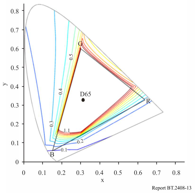
FIGURE 13 — Extending the BT.709 camera colour gamut
图 13. 扩展 BT.709 相机的色域。
The technique can be used to ensure a closer match between BT.709 and BT.2100 cameras for colours that are close to the BT.709 colour volume boundary.
这一技术可用于在接近 BT.709 色彩体积边界的色彩上,让 BT.709 相机与 BT.2100 相机更好地匹配。
Where the SDR BT.709 camera output is only used for shading and as the input to an SDR to HDR format converter, the signal clippers can be fully relaxed to maximise the captured colour volume. Not all format converters and production infrastructure are capable of passing the sub-black and super-white signals.
当 SDR BT.709 相机输出仅用于明暗控制、并作为 SDR 到 HDR 格式转换器的输入时,可完全放开信号削波器,使所采集的色彩体积最大化。并非所有格式转换器和制作基础设施都能通过次黑和超白信号。
5.5 Use of 8-bit content
5.5 8 比特内容的使用
Although a minimum of 10-bits should be used for HDR production, there may be occasions when it might not be possible to avoid including 8-bit SDR content within an HDR programme. In such cases, care should be taken if up-mapping rather than direct-mapping is used to place the content into an HDR signal container. The up-mapping process typically expands the SDR highlights. The 8-bit resolution, compounded by any 8-bit video compression, will limit the amount of highlight expansion that can be applied before banding and other artefacts become visible.
虽然 HDR 制作至少应使用 10 比特,但有时可能无法避免把 8 比特 SDR 内容纳入 HDR 节目。这种情况下,若采用上映射而非直接映射把内容装入 HDR 信号容器,就要格外小心。上映射过程通常会扩展 SDR 高光。8 比特的分辨率,再叠加任何 8 比特视频压缩,会限制在条带及其他伪影变得可见之前所能施加的高光扩展量。
6 Conversion between PQ and HLG
6 PQ 与 HLG 之间的转换
6.1 Transcoding concepts
6.1 转码概念
Transcoding aims to produce identical display light when the transcoded signal is reproduced on a display of the same peak luminance as the original signal. This section describes how a PQ signal may be transcoded to an HLG signal and vice versa, although cascaded conversions are to be discouraged to avoid risking loss of quality.
转码的目标是:当转码后的信号在与原始信号峰值亮度相同的显示设备上重现时,产生完全相同的显示光。本节描述如何把 PQ 信号转码为 HLG 信号、以及反向转码,但不提倡级联转换,以免冒损失质量的风险。
Figure 14 illustrates the concept behind transcoding from the PQ signal to the HLG signal. The PQ signal is decoded by the PQ EOTF to yield a signal that represents linear display light. This signal is then encoded by the HLG inverse EOTF to produce an equivalent HLG signal. When this HLG signal is subsequently decoded by the HLG EOTF in the display, the result will be the same display light that would be produced by decoding the original PQ signal with the PQ EOTF. The HLG inverse EOTF is the HLG inverse OOTF followed by the HLG OETF.
图 14 示意从 PQ 信号转码为 HLG 信号背后的原理。PQ 信号由 PQ EOTF 解码,得到一个代表线性显示光的信号;该信号再由 HLG 逆 EOTF 编码,产生等效的 HLG 信号。当这个 HLG 信号随后在显示设备中由 HLG EOTF 解码时,所得结果与用 PQ EOTF 解码原始 PQ 信号所产生的显示光相同。HLG 逆 EOTF 就是 HLG 逆 OOTF 后接 HLG OETF。
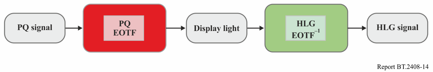
FIGURE 14 — Concept of transcoding from PQ to HLG
图 14. 从 PQ 转码为 HLG 的原理。
Figure 15 illustrates the concept behind the transcoding from the HLG signal to the PQ signal. The HLG signal is decoded by the HLG EOTF to yield a signal that represents linear display light. This signal is then encoded by the PQ inverse EOTF to produce an equivalent PQ signal. When this PQ signal is subsequently decoded by the PQ EOTF in the display, the result will be the same display light that would be produced by decoding the original HLG signal with the HLG EOTF.
图 15 示意从 HLG 信号转码为 PQ 信号背后的原理。HLG 信号由 HLG EOTF 解码,得到一个代表线性显示光的信号;该信号再由 PQ 逆 EOTF 编码,产生等效的 PQ 信号。当这个 PQ 信号随后在显示设备中由 PQ EOTF 解码时,所得结果与用 HLG EOTF 解码原始 HLG 信号所产生的显示光相同。
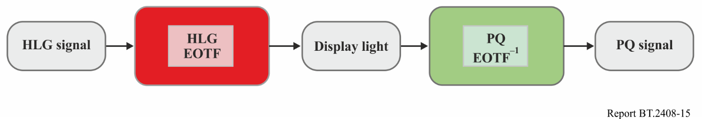
FIGURE 15 — Concept of transcoding from HLG to PQ
图 15. 从 HLG 转码为 PQ 的原理。
6.2 Conversion concepts using a reference condition at 1 000 cd/m2
6.2 以 1 000 cd/m² 为参考条件的转换概念
The transcoding concepts in the previous section produce the same displayed light for both PQ and HLG signals only when they are viewed on displays with the same peak luminance.
上一节的转码概念,只有当 PQ 与 HLG 信号在峰值亮度相同的显示设备上观看时,才会为二者产生相同的显示光。
However, the difference in the way that PQ and HLG signals are rendered on displays of different peak luminance complicates the conversions between PQ and HLG signals. If, for example, PQ signals, representing different peak luminances, are simply transcoded to HLG, the signal level for diffuse white will vary. Similarly, when HLG content is transcoded to PQ the brightness of diffuse white will vary depending on the assumed peak luminance of the HLG display.
然而,PQ 与 HLG 信号在不同峰值亮度显示设备上的呈现方式不同,这使 PQ 与 HLG 信号之间的转换变得复杂。例如,若把代表不同峰值亮度的 PQ 信号简单转码为 HLG,漫反射白的信号电平就会变化。同样,把 HLG 内容转码为 PQ 时,漫反射白的亮度会随所假定的 HLG 显示设备峰值亮度而变化。
To avoid such brightness changes, it is needed to convert, rather than simply transcode, the signals. Consistent brightness in the converted signals may be achieved by choosing a reference peak displayed luminance (LW) for the HLG signal, and requiring that PQ signal be limited to the same peak luminance. With these constraints consistent brightness is achieved in the converted signals. Therefore it is desirable that conversion between PQ and HLG should take place using the same reference peak displayed luminance for the signals used in the conversion. There is currently an industry consensus that this common peak luminance should be 1 000 cd/m2.
要避免这种亮度变化,就需要对信号进行“转换”,而非简单“转码”。为 HLG 信号选定一个参考峰值显示亮度(L_W),并要求 PQ 信号限制到相同的峰值亮度,即可使转换后的信号亮度保持一致。在这些约束下,转换后的信号便能获得一致的亮度。因此,PQ 与 HLG 之间的转换,宜对参与转换的信号采用相同的参考峰值显示亮度。目前业界共识是,这一共同峰值亮度应为 1 000 cd/m²。
For both transcoding and conversion a black level for the HLG EOTF also needs to be specified. The HLG black level, LB, should be set to zero for transcoding and conversion.
无论转码还是转换,都还需要为 HLG EOTF 规定一个黑位。转码和转换时,HLG 黑位 L_B 都应设为零。
With the choice of 1 000 cd/m2 as the common peak luminance, the conversion outlined above is completely specified for any HLG signal to PQ and, for PQ signals not exceeding 1 000 cd/m2, from PQ to HLG. Figure 16 illustrates the conversion from PQ to HLG.
选定 1 000 cd/m² 作为共同峰值亮度后,上述转换对任何 HLG 到 PQ 的转换、以及对不超过 1 000 cd/m² 的 PQ 到 HLG 转换,都得到了完整的规定。图 16 示意从 PQ 到 HLG 的转换。
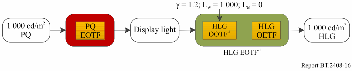
FIGURE 16 — Conversion from PQ to HLG at a common peak luminance of 1 000 cd/m2
图 16. 在 1 000 cd/m² 共同峰值亮度下从 PQ 到 HLG 的转换。
The following is an elaboration of Fig. 16 in terms of the three most fundamental transformations:
(1) The PQ EOTF and its inverse
(2) The HLG OETF and its inverse
(3) The HLG OOTF and its inverse.
The HLG EOTF is derived from (2) and (3). The Figure also includes the parameters for HLG OOTF-1. The resulting HLG signal will produce images identical to the original PQ images for all content that is within the colour volume of the 1 000 cd/m2 HLG reference display.
下面用三种最基本的变换来详述图 16:
- PQ EOTF 及其逆;
- HLG OETF 及其逆;
- HLG OOTF 及其逆。
HLG EOTF 由(2)和(3)推导而得。图中还给出了 HLG OOTF⁻¹ 的参数。对于处于 1 000 cd/m² HLG 参考显示设备色彩体积之内的所有内容,所得 HLG 信号产生的图像将与原始 PQ 图像完全相同。
Analogously, the conversion from HLG to PQ at 1 000 cd/m2 is the inverse of the above as illustrated in Fig. 17.
类似地,在 1 000 cd/m² 下从 HLG 到 PQ 的转换是上述过程的逆,如图 17 所示。
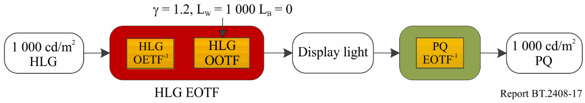
FIGURE 17 — Conversion from HLG to PQ at a common peak luminance of 1 000 cd/m2
图 17. 在 1 000 cd/m² 共同峰值亮度下从 HLG 到 PQ 的转换。
This conversion always produces a PQ image identical to HLG.
这一转换始终产生与 HLG 完全相同的 PQ 图像。
6.3 Cameras using a common OOTF at a reference peak luminance of 1 000 cd/m2
6.3 在 1 000 cd/m² 参考峰值亮度下使用共同 OOTF 的相机
Cameras could apply a common OOTF to produce PQ and HLG signals with identical displayed images at a reference peak luminance of Lw = 1 000 cd/m2.
相机可施加一个共同的 OOTF,从而产生在参考峰值亮度 L_W = 1 000 cd/m² 下显示图像完全相同的 PQ 和 HLG 信号。
This OOTF could be the PQ OOTF, or the HLG OOTF, and might include additional modifications applied in the camera, as illustrated in Fig. 18. PQ and HLG signals are obtained using their respective inverse EOTFs.
这一 OOTF 可以是 PQ OOTF,也可以是 HLG OOTF,还可能包含在相机内施加的额外修改,如图 18 所示。PQ 和 HLG 信号则分别用各自的逆 EOTF 得到。
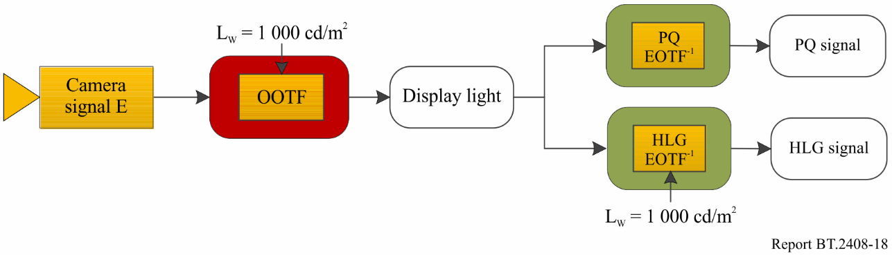
FIGURE 18 — Use of a common OOTF to provide both PQ and HLG at a common peak luminance of 1 000 cd/m2
图 18. 使用共同 OOTF 在 1 000 cd/m² 共同峰值亮度下同时提供 PQ 和 HLG。
The appearance of the displayed images will be the same on displays with a peak luminance capability of 1 000 cd/m2, for both the PQ and HLG signals. The appearance of the image is determined by the OOTF.
在峰值亮度能力为 1 000 cd/m² 的显示设备上,PQ 与 HLG 两种信号所显示图像的观感将完全相同。图像的观感由 OOTF 决定。
6.4 Handling PQ signals with greater than 1 000 cd/m2 peak luminance
6.4 处理峰值亮度大于 1 000 cd/m² 的 PQ 信号
PQ signals can represent a peak luminance of up to 10 000 cd/m2. In order to enable the reference conversion described above, PQ content must be limited to have a peak luminance that does not exceed 1 000 cd/m2. There are, in general, three approaches to achieving this:
(1) Clip to 1 000 cd/m2
(2) Static mapping to 1 000 cd/m2 (e.g. using an EETF curve like those described in § 3.1.1)
(3) Dynamic mapping to 1 000 cd/m2
PQ 信号最高可表示 10 000 cd/m² 的峰值亮度。为实现上述参考转换,必须把 PQ 内容限制到峰值亮度不超过 1 000 cd/m²。一般有三种做法:
- 削波到 1 000 cd/m²;
- 静态映射到 1 000 cd/m²(例如使用 3.1.1 节所述的 EETF 曲线);
- 动态映射到 1 000 cd/m²。
The first method, clipping to 1 000 cd/m2, is simple to implement. While multiple round trip conversions between PQ and HLG are to be discouraged, with this method content undergoes no additional limiting/clipping in the event of multiple round-trip conversions (i.e. PQ->HLG->PQ->HLG) beyond the initial clipping.
第一种方法——削波到 1 000 cd/m²——实现简单。虽然不提倡在 PQ 与 HLG 之间多次往返转换,但用这种方法时,内容在多次往返转换(即 PQ→HLG→PQ→HLG)中,除最初一次削波外,不会再经受额外的限幅/削波。
The second method, static mapping to 1 000 cd/m2 can be implemented by a LUT containing an EETF such as that described in § 3.1.1. While this avoids hard clipping of detail in the highlights, it is not invariant under blind multiple round-trip conversions.
第二种方法——静态映射到 1 000 cd/m²——可由一个包含 EETF(如 3.1.1 节所述)的 LUT 实现。它虽避免了对高光细节的硬削波,但在盲目的多次往返转换下并不保持不变。
The third method, dynamic mapping to 1 000 cd/m2, utilizes adaptive processing, for example on a frame-by-frame, or scene-by-scene basis. An adaptive algorithm could vary the EETF described in § 3.1.1 based on statistics of the image content (scene maximum for example). For non-live content, dynamic mappings could be generated offline by the content producer (either manually or using algorithmic processing). Except for the initial stage of limiting the PQ signal to 1 000 cd/m2, this approach could survive multiple round-trip conversions, because subsequent dynamic processing should be inactive given that the signal would already have been limited to 1 000 cd/m2.
第三种方法——动态映射到 1 000 cd/m²——采用自适应处理,例如逐帧或逐场景进行。自适应算法可根据图像内容的统计量(如场景最大值)来改变 3.1.1 节所述的 EETF。对非直播内容,动态映射可由内容制作者离线生成(人工或借助算法处理)。除最初把 PQ 信号限制到 1 000 cd/m² 这一步外,这种方法可经受多次往返转换,因为信号既已被限制到 1 000 cd/m²,后续的动态处理理应不再起作用。
6.5 Possible colour differences when converting from PQ to HLG
6.5 由 PQ 转换为 HLG 时可能出现的色差
In principle, the conversion of PQ images to HLG could give rise to hue shifts or desaturation on bright highly saturated areas of the picture, although such effects are believed to be rare in practice. Mathematically, this arises because the OOTF applied in the display for HLG is a function of overall luminance rather than identical functions of R, G, and B. Consider the equations for luminance in both the display and scene domains along with the EOTF for HLG:
原则上,把 PQ 图像转换为 HLG 可能在画面明亮、高饱和的区域引起色相偏移或去饱和,尽管一般认为这类效应在实践中很少见。从数学上看,这是因为 HLG 在显示端所施加的 OOTF 是整体亮度的函数,而不是对 R、G、B 各自相同的函数。考察显示域和场景域的亮度公式以及 HLG 的 EOTF:
Table 7 summarizes the peak values that can be displayed for pure white, and for the red, green and blue primaries, for a 1 000 cd/m2 PQ monitor, and for a 1 000 cd/m2 nominal peak HLG monitor. The Table shows values of ‘x’ such that when the non-linear signal values R = G = B = x the resulting white is 1 000 cd/m2. For PQ, this occurs when x is approximately 0.75; for a 1 000 cd/m2 HLG display, this occurs when x = 1.0. For a 1 000 cd/m2 PQ display, the maximum luminance of each of these colours is calculated using YD and is shown in the middle column of the Table. For HLG. the EOTF can be simplified by normalizing scene colours within [0:1]. Thus:
表 7 汇总了在 1 000 cd/m² PQ 监视器和 1 000 cd/m² 标称峰值 HLG 监视器上,纯白以及红、绿、蓝基色所能显示的峰值。表中给出使非线性信号值 R = G = B = x 时所得白为 1 000 cd/m² 的 x 值:对 PQ,约在 x = 0.75 时出现;对 1 000 cd/m² HLG 显示设备,则在 x = 1.0 时出现。对 1 000 cd/m² PQ 显示设备,这些色彩各自的最大亮度用 Y_D 计算,列于表的中间一列。对 HLG,可把场景色彩归一化到 [0, 1] 来简化 EOTF,于是:
When x = 1, so is the normalized scene colour and its non-linear representation, E , for the given component. This determines {𝑅𝐷 , 𝐺𝐷 , 𝐵𝐷 } and the resulting luminance is calculated using 𝑌𝐷. However, in production, HLG signals usually adopt the narrow range quantization levels specified in Recommendation ITU-R BT.2100. As noted in § 6.1 of Report ITU-R BT.2390, the conventional ‘narrow range’ digital signal can support signal levels of up to 109% of nominal full scale when carried as 10-bit or 12-bit signals (E = 1.090). So, the extended signal range between E = 1.0 and E = 1.090, sometimes referred to as ‘super-whites’, may be used to increase the HLG colour volume. The rightmost column in the Table shows the HLG maximum signal level required to match the displayed luminance of a 1 000 cd/m2 PQ display. Thus, they also represent the HLG signal ranges necessary to precisely convert a 1 000 cd/m2 PQ signal to HLG without clipping, thereby eliminating any risk of hue shifts or desaturation.
当 x = 1 时,给定分量的归一化场景色彩及其非线性表示 E 也都为 1。由此确定 {R_D, G_D, B_D},所得亮度用 Y_D 计算。然而在制作中,HLG 信号通常采用建议书 ITU-R BT.2100 规定的窄范围量化电平。正如报告 ITU-R BT.2390 第 6.1 节所指出的,常规“窄范围”数字信号以 10 比特或 12 比特承载时,可支持高达标称满量程 109% 的信号电平(E = 1.090)。因此,E = 1.0 到 E = 1.090 之间这段扩展信号范围(有时称为“超白”)可用来增大 HLG 色彩体积。表中最右一列给出匹配 1 000 cd/m² PQ 显示设备显示亮度所需的 HLG 最大信号电平;它们也代表了把 1 000 cd/m² PQ 信号精确转换为 HLG 而不削波所必需的 HLG 信号范围,从而消除任何色相偏移或去饱和的风险。
表 7. 在 1 000 cd/m² 标称峰值亮度显示设备上 PQ 与 HLG 的信号范围及可达色彩体积
| 色彩 | BT.2100 PQ,Y(cd/m²),1 000 cd/m² 峰值白,x = 0.75 | BT.2100 HLG,Y(cd/m²),x = 1.0 | 匹配 PQ 亮度所需的最大非线性信号 E |
|---|---|---|---|
| {x,x,x} 峰值白 | 1 000.0 | 1 000.0 | R = G = B = 1.000 |
| {x,0,0} 峰值红 | 262.7 | 201.1 | R = 1.041 |
| {0,x,0} 峰值绿 | 678.0 | 627.3 | G = 1.012 |
| {0,0,x} 峰值蓝 | 59.3 | 33.7 | B = 1.086 |
NOTE – In practice some displays might not achieve a luminance output higher than their nominal peak value.
注——实践中,有些显示设备可能无法达到高于其标称峰值的亮度输出。
By exploiting the quantization levels above E = 1.0, HLG is able to deliver the same 1 000 cd/m2 colour volume as PQ, without clipping. This could be particularly useful when converting graded PQ content to HLG. Furthermore, the peak luminance for white on an HLG reference display is increased from 1 000 cd/m2 to 1 811 cd/m2.
通过利用 E = 1.0 以上的量化电平,HLG 能在不削波的情况下提供与 PQ 相同的 1 000 cd/m² 色彩体积。这在把已调色的 PQ 内容转换为 HLG 时可能尤为有用。此外,HLG 参考显示设备上白的峰值亮度也从 1 000 cd/m² 提高到 1 811 cd/m²。
NOTE – The HLG OOTF system gamma is still calculated using the display’s nominal peak luminance at x = 1.0.
注——HLG OOTF 的系统伽马仍按 x = 1.0 处显示设备的标称峰值亮度来计算。
7 Transitioning from SDR to HDR production
7 从 SDR 制作向 HDR 制作过渡
During the transition from SDR to HDR production, the majority of viewers will be watching in SDR, so it is important that the SDR production is not significantly compromised by the introduction of HDR. It is, however, unlikely to be economic or practical to cover live programmes and events with totally independent HDR and SDR production facilities. As well as the cost of the two productions, there may simply be insufficient camera positions available for both HDR and SDR cameras.
在从 SDR 制作向 HDR 制作过渡期间,大多数观众仍以 SDR 观看,因此务必不能因引入 HDR 而显著损害 SDR 制作。然而,用两套完全独立的 HDR 与 SDR 制作设备去覆盖直播节目和赛事,既不经济也不现实。除两套制作的成本外,可能根本没有足够的机位同时容纳 HDR 与 SDR 相机。
Native HDR production architectures highlighting either HDR or SDR focused production are illustrated in Figs 20 and 21. Over time, as audiences adopt HDR television displays designed for BT.2100 signals, production architectures may be expected to shift from focusing on delivering primarily for SDR, to delivering primarily for HDR.
图 20 和图 21 分别给出以 HDR 为重心、以 SDR 为重心的原生 HDR 制作架构。随着时间推移,当观众逐渐采用为 BT.2100 信号设计的 HDR 电视显示设备后,制作架构预计会从以主要交付 SDR 为重心,转向以主要交付 HDR 为重心。
Note that in both production architectures the eye may adapt to the brighter HDR monitor, affecting the appearance of signals on the dimmer SDR screen. So, the HDR and SDR screens should be physically separated for critical assessment of the SDR signal.
需要注意,在这两种制作架构中,眼睛都可能适应较亮的 HDR 监视器,从而影响较暗 SDR 屏幕上信号的观感。因此,为对 SDR 信号作关键评估,HDR 与 SDR 屏幕应在物理上分开放置。
Alternative optional monitoring techniques may be used to compare HDR and SDR:
也可采用其他可选的监看手段来比较 HDR 与 SDR:
• Where there is only a single display, it can be switched back and forth between HDR and SDR to compare images. In this case, adjustments may be required to the HLG or SDR luminance and/or gamma setting to unify diffuse white levels.
- 当只有一台显示设备时,可在 HDR 与 SDR 之间来回切换以比较图像。这种情况下,可能需要调整 HLG 或 SDR 的亮度和/或伽马设置,以统一漫反射白的电平。
• Where there are multiple displays (or a single display capable of simultaneous display of multiple EOTFs), side-by-side monitoring techniques can be used, where both HDR and SDR displays are used in close proximity. For the images to be side-by-side, the differences in diffuse white level need to be unified.
- 当有多台显示设备(或单台能同时显示多种 EOTF 的显示设备)时,可采用并排监看手段,把 HDR 与 SDR 显示设备近距离并置。要让两幅图像并排可比,需统一二者漫反射白电平的差异。
Dual-focused HDR production with diffuse white level unification adjustment as described in Recommendation ITU-R BT.2166 is illustrated in Fig. 22 and introduced in § 7.4. More detail and examples using these methods are described in Annexes 9, 10 and 11.
按建议书 ITU-R BT.2166 所述、带漫反射白电平统一调整的双重心 HDR 制作,见图 22,并在 7.4 节作介绍。运用这些方法的更多细节和示例见附件 9、10 和 11。
Where a single production distributes HDR content for international exchange, and where the downstream broadcaster derives the SDR version, the up- and down-mapping methods used in the production are a serious consideration for ensuring the correct mapping for versions derived by third parties. It is desirable that the upstream mapping in production matches those used by broadcast facilities where content is shared across territories. Furthermore, when this content is shared across territories, it is essential that the downstream broadcast facilities are aware of the down-mapper used in the upstream production.
当单一制作把 HDR 内容用于国际交换分发、并由下游广播机构导出 SDR 版本时,制作中所用的上映射和下映射方法,对确保第三方所导出版本的映射正确至关重要。内容跨地区共享时,上游制作所用的映射,最好与各广播设施所用的相一致。此外,当内容跨地区共享时,下游广播设施必须了解上游制作所用的下映射器。
7.1 Common components in a single-master workflow
7.1 单母版工作流中的共同环节
7.1.1 UHD and HD resolution HDR camera outputs
7.1.1 UHD 与 HD 分辨率的 HDR 相机输出
Early trials of HLG HDR production often employed a parallel production workflow, comprising a UHD HDR ‘layer’ and an HD SDR ‘layer’. Many HDR cameras conveniently provide parallel UHD HDR and HD SDR outputs to facilitate such productions. Unfortunately, artistic or operational adjustments made by viewing one of the camera outputs do not always track in the other output. So, where both HDR and SDR programme outputs are required from a production, the SDR output is usually derived from the HDR output via a down-mapping conversion.
HLG HDR 制作的早期试验常采用并行制作工作流,包含一个 UHD HDR“层”和一个 HD SDR“层”。许多 HDR 相机为便于这类制作,会同时提供并行的 UHD HDR 和 HD SDR 输出。可惜的是,通过监看其中一路相机输出所作的艺术性或操作性调整,并不总能在另一路输出中同步体现。因此,当一档制作同时需要 HDR 和 SDR 节目输出时,SDR 输出通常通过下映射转换由 HDR 输出导出。
Whilst such a conversion is possible at UHD resolution for the main programme output, UHD conversion may become impractical for large productions where a ‘host broadcaster’ may have to provide many HD resolution SDR ISO (isolated) camera feeds to rights holding broadcasters (RHBs). So, the HDR camera’s native SDR outputs were most often used for the SDR ISO lines. The same SDR outputs were also used for camera shading on an SDR monitor.
虽然主节目输出的这种转换可在 UHD 分辨率下进行,但对于大型制作,UHD 转换可能不切实际——此时“主办广播机构”可能须向持权广播机构(RHB)提供许多路 HD 分辨率的 SDR ISO(独立)相机馈送。因此,HDR 相机的原生 SDR 输出最常被用作 SDR ISO 线路。同样的 SDR 输出也用于在 SDR 监视器上进行摄像机明暗控制。
In order to ensure that the main SDR programme output derived via a down-mapper matches the SDR ISO feeds provided by the cameras’ SDR outputs, a scene-light down-mapping from the HLG signal is required. Unfortunately, a scene-light conversion does not preserve the ‘look’ of the HLG input. The SDR outputs derived through the scene-light conversion are more colourful, and have subjectively ‘punchier’ midtones, than the HDR original, see § 7.6.3 and Annex 6. Moreover, where artistic adjustments are made to the cameras using the native SDR outputs, or even a scene-light down-mapped version of an HDR camera, the HDR can look ‘flat’ and desaturated in comparison with the adjusted SDR output.
为确保经下映射器导出的主 SDR 节目输出,与各相机 SDR 输出所提供的 SDR ISO 馈送相匹配,需要对 HLG 信号作场景光下映射。可惜场景光转换并不保留 HLG 输入的“观感”:经场景光转换导出的 SDR 输出比 HDR 原始画面更鲜艳,中间调在主观上更“有冲击力”,见 7.6.3 节和附件 6。此外,若通过原生 SDR 输出(甚至是 HDR 相机的场景光下映射版本)对相机作艺术性调整,则与调整后的 SDR 输出相比,HDR 可能显得“发平”、饱和度不足。
The addition of HD resolution HDR outputs from cameras has greatly improved the consistency of HDR and SDR outputs from a production as,
• it becomes practical to derive SDR camera ISO feeds and SDR shading signals from the camera’s HD (1080p) HDR output via a down-mapper, avoiding any SDR/HDR output tracking issues;
• the down-mapper can be based on display-light rather than scene-light, thereby matching the ‘look’ of the HDR and SDR outputs.
相机增加 HD 分辨率的 HDR 输出后,大大改善了一档制作中 HDR 与 SDR 输出的一致性,因为:
- 可以切实地经下映射器,从相机的 HD(1080p)HDR 输出导出 SDR 相机 ISO 馈送和 SDR 明暗控制信号,从而避免任何 SDR/HDR 输出不同步的问题;
- 下映射器可基于显示光而非场景光,从而使 HDR 与 SDR 输出的“观感”相匹配。
7.1.2 HDR slow-motion
7.1.2 HDR 慢动作
Slow-motion cameras are usually placed in key camera positions. They run at an integer multiple of the production frame-rate but provide their output as different ‘phases’ of the production frame-rate. A single phase is often used as a live camera position, and multiple phases recorded in parallel to provide slow-motion replays. While such cameras were limited to standard dynamic range capture, the sheer number of phases that needed recording would often prohibit the use of SDR to HDR conversion prior to recording. So, action replay servers were usually limited to SDR record and replay. As those same replay servers are often used for pre-recorded programme inserts, those would have to be limited to SDR too. Moreover, for large productions a ‘host broadcaster’ would usually make one of the slow-motion camera’s phases available as an SDR ISO camera feed to other rights holding broadcasters (RHBs).
慢动作相机通常放在关键机位。它们以制作帧率的整数倍运行,但以制作帧率的不同“相位”形式输出。常把单个相位用作直播机位,同时并行记录多个相位以提供慢动作回放。当这类相机仅限标准动态范围采集时,需要记录的相位数量之多,往往使人无法在记录前进行 SDR 到 HDR 的转换。因此,动作回放服务器通常只限于 SDR 记录和回放。由于这些回放服务器也常用于预录节目的插入,那些插入素材也只能限于 SDR。此外,对大型制作,“主办广播机构”通常会把慢动作相机的某个相位作为 SDR ISO 相机馈送提供给其他持权广播机构(RHB)。
The availability of HDR slow-motion cameras has greatly reduced the number of SDR cameras used in an HDR production. It has allowed replay servers to be switched from SDR to HDR, greatly simplifying the production workflow, whilst also allowing HDR pre-recorded programme inserts. As with other HDR cameras, a single-phase from the slow-motion camera can be provided as an SDR ISO feed to other broadcasters via a display-light down-mapper.
HDR 慢动作相机的出现,大大减少了 HDR 制作中所用 SDR 相机的数量。它使回放服务器得以从 SDR 切换到 HDR,大大简化了制作工作流,同时也允许 HDR 预录节目插入。与其他 HDR 相机一样,慢动作相机的单个相位可经显示光下映射器,作为 SDR ISO 馈送提供给其他广播机构。
7.1.3 HDR to SDR down-mapping
7.1.3 HDR 到 SDR 的下映射
In any large production, SDR to HDR to SDR ‘round-trip’ losses are a major concern. Any native SDR content included in the production should pass through the production infrastructure to SDR outputs with minimal loss. At the same time, however, programme makers may wish SDR viewers to benefit from the HDR production by reserving some of the SDR output signal range for the compressed highlights captured by the HDR cameras. Thus, it is not uncommon for SDR content directly mapped into HLG at the ‘HDR Reference White’ level of 75% to be attenuated on the SDR output to as little as 86% (a 14% loss). The remaining signal range carries compressed highlights from HDR sources.
在任何大型制作中,SDR→HDR→SDR 的“往返”损失都是一大关切。制作中纳入的任何原生 SDR 内容,都应以最小的损失穿过制作基础设施到达 SDR 输出。但与此同时,节目制作者可能希望让 SDR 观众也从 HDR 制作中获益,办法是在 SDR 输出信号范围中保留一部分,用于承载 HDR 相机所采集、经压缩的高光。因此,把 SDR 内容按 75% 的“HDR 参考白”电平直接映射进 HLG 后,在 SDR 输出端被衰减到低至 86%(损失 14%)的情况并不少见。余下的信号范围用来承载来自 HDR 源的压缩高光。
So, in order to reduce round-trip losses, SDR content would often be up-mapped rather than directly-mapped into the HDR container, complementing the tone-mapping curve in the output down-mapper. However, results from SDR up-mapping can be variable. While it may work well for carefully produced non-live content, live content often contains large areas of clipped highlights that up-map less well.
因此,为减少往返损失,往往把 SDR 内容上映射(而非直接映射)进 HDR 容器,以与输出下映射器中的色调映射曲线互补。不过,SDR 上映射的结果可能参差不齐。它对精心制作的非直播内容或许效果良好,但直播内容常含大片被削掉的高光,上映射效果较差。
To address the problem, several down-mappers now make use of the SDR ‘super-white’ signal range up to 109% to carry the compressed highlights from the HDR cameras. By doing so, they need to reserve far less of the nominal SDR signal range for HDR highlights, which in turn reduces the round-trip losses for directly-mapped SDR sources. EBU Recommendation R.103 [5] defines a “preferred signal range” with an upper limit of ~105%, which it is generally safe for down-mappers to use. By doing so, round-trip losses for direct-mapped SDR content may be reduced to as low as 5%.
为解决这一问题,目前有若干下映射器利用高达 109% 的 SDR“超白”信号范围来承载 HDR 相机的压缩高光。这样一来,它们只需在标称 SDR 信号范围中为 HDR 高光保留少得多的部分,从而减少了直接映射 SDR 源的往返损失。EBU 建议书 R.103 [5] 定义了上限约为 105% 的“优选信号范围”,下映射器使用它通常是安全的。如此一来,直接映射 SDR 内容的往返损失可降至低达 5%。
7.1.4 Camera shading
7.1.4 摄像机明暗控制
To ensure the highest quality priority programme output and camera alignment, camera shading is carried out using one of the methods described below.
为确保优先级最高的节目输出质量以及相机校准,摄像机明暗控制采用下述方法之一进行。
– Using an HDR-focused workflow where the quality of the HDR programme output is therefore priority, shading will be carried out using HDR monitors and/or HDR waveform monitors/vectorscopes. SDR monitoring should be separated to avoid eye adaptation issues.
- 采用以 HDR 为重心的工作流(HDR 节目输出质量因此为优先)时,明暗控制借助 HDR 监视器和/或 HDR 波形监视器/矢量示波器进行。SDR 监看应分开放置,以避免眼睛适应问题。
– Using an SDR-focused workflow, to ensure the highest quality SDR output, cameras use an SDR monitor fed with identical HDR to SDR down-mappers to those used on the main programme’s derived-SDR distribution output. HDR monitoring should be separated to avoid eye adaptation issues.
- 采用以 SDR 为重心的工作流(以确保最高质量的 SDR 输出)时,相机使用一台 SDR 监视器,其馈入所用的 HDR 到 SDR 下映射器,与主节目所导出 SDR 分发输出所用的完全相同。HDR 监看应分开放置,以避免眼睛适应问题。
– Using a dual-focused HDR/SDR workflow with monitoring techniques defined in Recommendation ITU-R BT.2166 where:
• SDR monitors are fed with identical HDR to SDR down-mappers to those used on the main programme’s derived-SDR distribution output.
• HDR and SDR monitors are placed in close proximity.
- 采用双重心 HDR/SDR 工作流(监看手段按建议书 ITU-R BT.2166 定义)时:
- SDR 监视器所馈入的 HDR 到 SDR 下映射器,与主节目所导出 SDR 分发输出所用的完全相同;
- HDR 与 SDR 监视器近距离并置。
The following describes a typical shading process for live television.
下面描述电视直播中典型的明暗控制流程。
7.1.5 Technical and perceptual line-up options
7.1.5 技术校线与感知校线选项
Technical line-up uses a waveform monitor to ensure objects with a particular reflectance are at the correct signal level, typically using some element of midtone and diffuse white to set HDR camera exposure. Perceptual line-up uses visually subjective cues for image adjustments on a display.
技术校线借助波形监视器确保特定反射率的物体处于正确的信号电平,通常用某种中间调元素和漫反射白来设定 HDR 相机的曝光。感知校线则依据视觉主观线索,在显示设备上对图像作调整。
– Diffuse-white levels viewed on a waveform monitor through a down-mapper can be used to determine basic exposure settings.
- 经下映射器在波形监视器上观察漫反射白电平,可用来确定基本的曝光设置。
– Perceptual adjustments can be used to achieve the desired level of SDR detail preservation when down-mapping HDR highlights and viewing on an SDR display.
- 在下映射 HDR 高光并于 SDR 显示设备上观看时,可用感知调整来达到所需的 SDR 细节保留程度。
– Focal midtones elements like grass, fleshtones, and other elements can be used by one or a team of shaders to align the camera exposure for optimally matched live switching.
- 草地、肤色等焦点中间调元素,可供一名或一组视频控制员用来校准相机曝光,使直播切换时各机位最佳匹配。
– Technical and perceptual elements are typically used in an interactive process to achieve the desired look.
- 技术与感知两方面通常在一个交互过程中并用,以达到所需的观感。
This section describes a process that sets exposure in tandem with the painting process which builds the final look with other adjustments including gamma, saturation, lift, etc.
本节描述的流程,是在设定曝光的同时进行调校(painting)——后者通过伽马、饱和度、提升(lift)等其他调整来构建最终观感。
In the case of live sports, key visual elements (e.g. grass, flesh tones) can be used as guidance to set SDR midtone levels. The choice of the down mapper will influence the exposure of the HDR camera when adjustments are made while monitoring SDR perceptually or technically. The differences are small and similar in magnitude to those arising through different artistic choices but could affect the corresponding diffuse white level along with preserved SDR detail. See § 5.2 for details of down-mapping methods and § 7.10 for details of camera painting.
以体育直播为例,可用关键视觉元素(如草地、肤色)作为指引来设定 SDR 中间调电平。在以感知或技术方式监看 SDR 并作调整时,下映射器的选择会影响 HDR 相机的曝光。这些差异不大,量级与不同艺术选择所造成的差异相当,但可能影响相应的漫反射白电平以及所保留的 SDR 细节。下映射方法详见 5.2 节,摄像机调校详见 7.10 节。
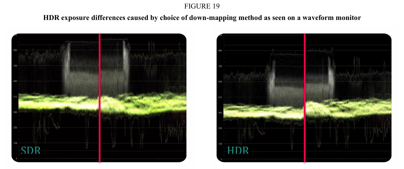
FIGURE 19 — HDR exposure differences caused by choice of down-mapping method as seen on a waveform monitor
图 19. 在波形监视器上所见、因下映射方法选择不同而造成的 HDR 曝光差异。
SDR — SDR Shading: Exposing for 50% SDR. Gamma Adjusted (left) and Hybrid-Linear (right). HDR — Resulting HDR Camera Exposure. Gamma Adjusted (left) and Hybrid-Linear (right).
左:SDR——SDR 明暗控制:按 50% SDR 曝光。伽马调整(左)与混合线性(右)。右:HDR——由此得到的 HDR 相机曝光。伽马调整(左)与混合线性(右)。
Changes in exposure of the image may be more visible in the HDR output than the SDR output. So rapid adjustments in exposure whilst shading in SDR should be avoided.
图像曝光的变化在 HDR 输出中可能比在 SDR 输出中更明显。因此在以 SDR 作明暗控制时,应避免快速调整曝光。
Under controlled studio lighting, a possible option may be to shade the cameras using the HLG backwards compatible SDR picture, rather than via a dedicated HDR to SDR converter. In this case, the SDR shading monitor should be set to a display gamma of 2.2 with BT.2020 colour, to resemble a typical display-light conversion from HLG to SDR as shown on a BT.1886 (gamma 2.4) production monitor. However, under variable lighting conditions or in territories where SDR skin tones are set brighter, a dedicated HDR to SDR converter is preferred.
在受控演播室照明下,一种可行的做法是用 HLG 向后兼容的 SDR 画面(而非专用的 HDR 到 SDR 转换器)来对相机作明暗控制。这种情况下,SDR 明暗控制监视器应设为显示伽马 2.2、BT.2020 色彩,以近似 BT.1886(伽马 2.4)制作监视器上所呈现的、由 HLG 到 SDR 的典型显示光转换。但在照明多变的条件下,或在 SDR 肤色设得更亮的地区,则宜采用专用的 HDR 到 SDR 转换器。
When using an SDR-focused workflow, the SDR monitors used for camera shading should be separated from the HDR check monitor that is used to ensure that high quality HDR output is being maintained (indicated as Vision Supervisor in Fig. 21). As an example, in a live production trial, occasional checks of the HDR output by a vision supervisor were found to be sufficient, with operators concentrating on the SDR monitors used for camera shading. Some productions prefer to use dual-focused monitoring with monitors set up as described in Recommendation ITU-R BT.2166 so that a shader can see both the HDR and SDR images simultaneously.
采用以 SDR 为重心的工作流时,用于摄像机明暗控制的 SDR 监视器,应与用于确保维持高质量 HDR 输出的 HDR 检查监视器(图 21 中标为“视频主管”)分开放置。举例来说,在一次直播制作试验中,由视频主管对 HDR 输出作偶尔检查即已足够,操作员则专注于用于摄像机明暗控制的 SDR 监视器。有些制作偏好采用双重心监看,按建议书 ITU-R BT.2166 所述布置监视器,使视频控制员能同时看到 HDR 与 SDR 图像。
7.2 Single-master HDR production with HDR-focused workflow
7.2 以 HDR 为重心的单母版 HDR 制作
For optimum quality HDR pictures, both HDR and SDR cameras should be shaded using an HDR monitor, as illustrated in Fig. 20. Nominal signal levels for shading are given in § 2.2. These may vary if camera painting controls are used to deliver a particular ‘look’. Where the prime delivery signal is to be BT.709 for existing HD distribution, there may be compromises in the SDR feed from HDR based production, so the SDR-focused workflow, or dual-focused workflow described in §§ 7.3 and 7.4 may be preferred.
为获得最优质量的 HDR 画面,HDR 与 SDR 相机都应借助 HDR 监视器作明暗控制,如图 20 所示。明暗控制的标称信号电平见 2.2 节。若使用摄像机调校控制项来呈现某种特定“观感”,这些电平可能有所变化。当主交付信号要用于现有 HD 分发的 BT.709 时,基于 HDR 制作所得的 SDR 馈送可能存在折中,因此 7.3 节和 7.4 节所述以 SDR 为重心的工作流或双重心工作流可能更可取。
As the exposure latitude of HDR images is far greater than SDR, a dynamic HDR to SDR converter may be required to deliver a satisfactory SDR output. A dynamic converter is designed to optimise the HDR to SDR tone mapping curve for any scene, thereby accommodating a wider range of exposures than might be possible with a fixed (or static) tone mapping curve.
由于 HDR 图像的曝光宽容度远大于 SDR,要交付令人满意的 SDR 输出,可能需要一台动态 HDR 到 SDR 转换器。动态转换器旨在为任何场景优化 HDR 到 SDR 的色调映射曲线,从而容纳比固定(或静态)色调映射曲线更宽的曝光范围。
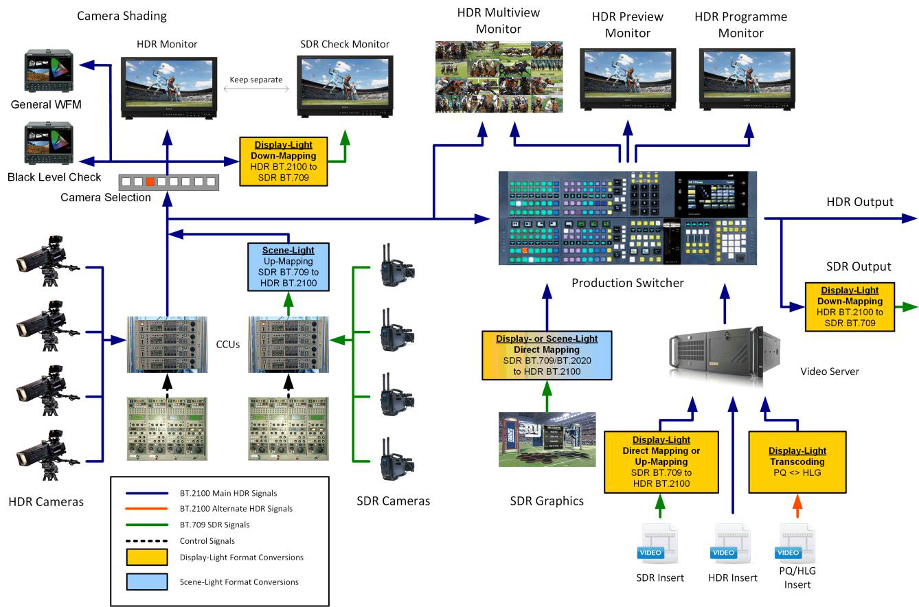
FIGURE 20 — Single-master HDR production with HDR-focused shading
图 20. 以 HDR 为重心作明暗控制的单母版 HDR 制作。
In this HDR focused production, BT.709 cameras may be included in the production by using the ‘scene-referred’ SDR direct-mapping technique, as described in § 5. To ensure a closer match between HDR and SDR cameras, up-mapping (which expands highlights in the SDR signal) may also be used. However, as highlights are often heavily clipped by SDR cameras, only a small amount of highlight expansion is likely to be possible, so direct-mapping is often preferred. Further colour match improvements can be made by relaxing the SDR signal clippers, as described in § 5.4.
在这种以 HDR 为重心的制作中,可按第 5 节所述,采用“场景参考”的 SDR 直接映射技术把 BT.709 相机纳入制作。为使 HDR 与 SDR 相机更好地匹配,也可使用上映射(它会扩展 SDR 信号中的高光)。不过,由于高光常被 SDR 相机大幅削掉,可能只能作少量高光扩展,因此往往更倾向于直接映射。如 5.4 节所述,放开 SDR 信号削波器可进一步改善色彩匹配。
In Fig. 20, all inputs to the production switcher are HDR. This removes the need to process separate HDR and SDR feeds throughout the production chain. Graphics may be inserted as per § 9. Work is currently underway to determine the best practice for HDR key signals. In the interim, using an SDR key signal directly has been found to deliver satisfactory results.
在图 20 中,制作切换台的所有输入都是 HDR。这样就无须在整条制作链路上分别处理 HDR 与 SDR 馈送。图形可按第 9 节插入。目前正在研究 HDR 键控信号的最佳实践;在此期间,直接使用 SDR 键控信号已被发现能取得令人满意的结果。
The primary output from the production switcher is HDR. The SDR output is derived via display referred (display-light) down-mapping. A display-light conversion should ensure that both the SDR and HDR signals have a similar look. A dynamic down-mapper may sometimes provide a more satisfactory SDR output than a static down-mapper, but attention should be paid to graphics which may need to be inserted after dynamic down-mapping, to ensure a fixed signal level. A scene-light HDR to SDR conversion may also be included (not shown in Fig. 20) where it is important to colour match the converted PQ or HLG output to downstream SDR BT.709 cameras. However, consideration should be given to potential changes in colour saturation and tones of graded content (see § 7.6.3). Ultimately, the choice of HDR to SDR down-mapping depends on the application.
制作切换台的主输出是 HDR。SDR 输出经显示参考(显示光)下映射导出。显示光转换应确保 SDR 与 HDR 信号具有相近的观感。动态下映射器有时能比静态下映射器提供更令人满意的 SDR 输出,但要注意图形——它们可能需要在动态下映射之后插入,以确保固定的信号电平。当需要把转换所得的 PQ 或 HLG 输出与下游 SDR BT.709 相机作色彩匹配时,也可加入场景光 HDR 到 SDR 转换(图 20 中未示出)。不过,应考虑到已调色内容在色彩饱和度和色调上可能出现的变化(见 7.6.3 节)。归根结底,HDR 到 SDR 下映射的选择取决于应用。
Differences in black level may be more visible in the down-mapped SDR signal than in the HDR signal, as glare from bright highlights in the HDR image can mask detail in the shadows. To help ensure a consistent black level in the HDR and down-converted SDR signals, a dedicated waveform monitor displaying the lower portion of the signal range is recommended.
黑位的差异在下映射所得的 SDR 信号中可能比在 HDR 信号中更明显,因为 HDR 图像中明亮高光的眩光会掩盖暗部细节。为帮助确保 HDR 与下变换 SDR 信号黑位的一致,建议使用一台专门显示信号范围低段的波形监视器。
7.3 Single-master HDR production with SDR focused workflow
7.3 以 SDR 为重心的单母版 HDR 制作
If the SDR production must not be compromised, both HDR and SDR cameras should be shaded using an SDR monitor fed via a display-light down-mapper. Whilst the HDR signals may not always exploit the full potential of the HDR production formats, the HDR pictures can still show significant improvement over the SDR pictures which are protected to ensure their optimal quality.
如果 SDR 制作绝不能受损,则 HDR 与 SDR 相机都应借助一台经显示光下映射器馈入的 SDR 监视器作明暗控制。虽然 HDR 信号未必总能发挥 HDR 制作格式的全部潜力,但在 SDR 画面的质量得到保护、确保其最优的同时,HDR 画面仍能比 SDR 画面有显著改善。
7.3.1 PQ production with SDR shading
7.3.1 以 SDR 明暗控制的 PQ 制作
SDR focused PQ production uses the same workflow as shown in Fig. 20 except:
• an SDR reference monitor is used for shading;
• the HDR shading monitor becomes the check monitor.
An additional scene-light PQ to SDR BT.709 conversion may also be included for colour matching with downstream SDR BT.709 cameras.
以 SDR 为重心的 PQ 制作采用与图 20 相同的工作流,但有以下不同:
- 明暗控制使用一台 SDR 参考监视器;
- 原 HDR 明暗控制监视器变为检查监视器。
为与下游 SDR BT.709 相机作色彩匹配,还可加入一路额外的场景光 PQ 到 SDR BT.709 转换。
7.3.2 HLG production with SDR shading
7.3.2 以 SDR 明暗控制的 HLG 制作
SDR-focused HLG production can use the same workflow as shown in Fig. 20 except:
• an SDR reference monitor is used for shading;
• the HDR monitor is used as a check monitor and may use peak luminance levels below those specified as reference in Recommendation ITU-R BT.2100.
以 SDR 为重心的 HLG 制作可采用与图 20 相同的工作流,但有以下不同:
- 明暗控制使用一台 SDR 参考监视器;
- HDR 监视器用作检查监视器,其峰值亮度电平可低于建议书 ITU-R BT.2100 规定的参考值。
The SDR-focused workflow is one in which the SDR image is derived from the HDR programme using one of the three common single-master workflows utilising live HLG production. This workflow has been facilitated by the introduction of:
• improvements in the use of defined HDR to SDR down-mapping;
• LUT based HDR to SDR down-mapping in multiview monitors;
The workflow addresses the requirements for use of existing monitoring facilities, simplicity and ensuring the SDR delivery is not compromised.
以 SDR 为重心的工作流,是指利用 HLG 直播制作的三种常见单母版工作流之一,从 HDR 节目导出 SDR 图像。以下进展促成了这一工作流:
- 改进了所定义的 HDR 到 SDR 下映射的使用;
- 在多画面监视器中采用基于 LUT 的 HDR 到 SDR 下映射。
该工作流满足了沿用现有监看设施、保持简便、并确保 SDR 交付不受损的诸项要求。
A typical SDR-focused workflow is illustrated in simplified form in Fig. 21.
图 21 以简化形式给出一种典型的以 SDR 为重心的工作流。
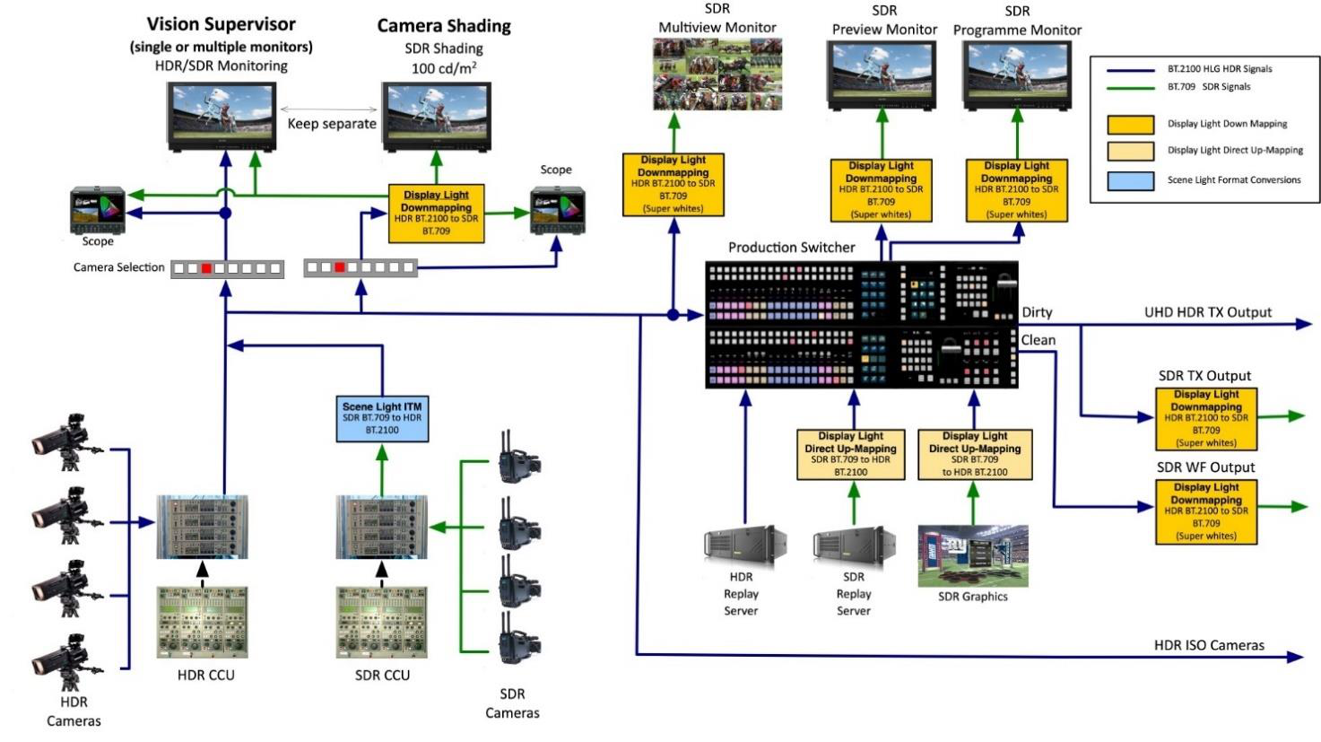
FIGURE 21 — Single-master HDR production using SDR-focused camera shading
图 21. 采用以 SDR 为重心摄像机明暗控制的单母版 HDR 制作。
A variation of this approach used in China is shown as an example in Annex 8.
中国采用的这一做法的一种变体作为示例见附件 8。
For any SDR outputs a display-light down-mapping conversion is strongly recommended, as that should ensure the same hue and saturation of images and graphics in both HDR and SDR outputs (see § 7.6.3). Most importantly, the down-mapper should be similar in nature, in particular in its treatment of shadow detail and midtones, to any down-mappers used by third-party broadcasters taking the HDR signal and deriving their own SDR versions of the programmes through a common down-mapper within their MCRs (Master Control Rooms). Suitable down-mappers are described in Report ITU-R BT.2446.
对任何 SDR 输出,都强烈建议采用显示光下映射转换,因为这应能确保 HDR 与 SDR 输出中图像和图形具有相同的色相和饱和度(见 7.6.3 节)。最重要的是,该下映射器在性质上、尤其在对暗部细节和中间调的处理上,应与第三方广播机构所用的任何下映射器相近——后者接收 HDR 信号,并在其总控室(MCR)内通过一个共同的下映射器导出各自的 SDR 节目版本。合适的下映射器见报告 ITU-R BT.2446。
Down-mapping (tone-mapping) when converting to SDR, rather than hard clipping, will allow the SDR output to benefit from the high dynamic range production by preserving some detail in the image highlights. A down-mapper that exploits the SDR ‘super-white’ signal range will reduce SDR>HDR>SDR round-trip losses (see §§ 7.6 and 7.7). So, these are often preferred for live productions, where round-trip losses can be a concern.
转换为 SDR 时采用下映射(色调映射)而非硬削波,可通过保留图像高光中的一些细节,使 SDR 输出也从高动态范围制作中获益。利用 SDR“超白”信号范围的下映射器能减少 SDR→HDR→SDR 的往返损失(见 7.6 节和 7.7 节)。因此,在往返损失可能成为顾虑的直播制作中,往往更倾向于使用这类下映射器。
As with Fig. 20, graded content should be inserted into the programme using display-light direct-mapping or up-mapping, to preserve its original ‘look’ and the artistic intent. However, where the HDR to SDR down-mapper exploits the SDR ‘super-white’ region, direct-mapping is usually preferred. SDR graphics should be directly mapped into the HDR format (as per § 9).
与图 20 一样,已调色内容应采用显示光直接映射或上映射插入节目,以保留其原有“观感”和艺术意图。不过,当 HDR 到 SDR 下映射器利用了 SDR“超白”区域时,通常更倾向于直接映射。SDR 图形应直接映射进 HDR 格式(按第 9 节)。
During the transition to full HDR production, it will be common to include SDR BT.709 cameras within a production. In order to match the colour and tone of native HLG cameras, scene-light direct-mapping should be used. Up-mapping for live camera sources is not recommended, due to the difficulty in avoiding large areas of clipped highlights.
在向完全 HDR 制作过渡期间,制作中纳入 SDR BT.709 相机将很常见。为匹配原生 HLG 相机的色彩和色调,应采用场景光直接映射。不建议对直播相机源作上映射,因为难以避免大片被削掉的高光。
7.4 Single-master HDR production with dual-focused workflow
7.4 双重心的单母版 HDR 制作
Where the goal is to simultaneously monitor HDR and SDR in order to balance the qualities of both image formats, a single-master production using dual-focused monitoring may be used. This is a variation of single-master HDR production that allows HDR and SDR images to be viewed simultaneously in close proximity while attempting to minimize eye adaptation issues. This production type requires that vision engineers and vision supervisors have access to HDR and SDR displays or images that are side-by-side. In this case, a matching diffuse white level is set between the HDR and SDR displays so that the displays or images can be viewed simultaneously in close proximity to determine the desired artistic intent. In order to achieve comparable perceptual brightness between SDR and HDR images on the displays, care should be taken with down-mapping characteristics when SDR images are derived from HDR images. This workflow uses monitoring where the HDR and SDR displays are in close proximity (as defined in Recommendation ITU-R BT.2166). There are two recommended methods. Their order should not be taken to indicate a preferred approach.
当目标是同时监看 HDR 和 SDR、以兼顾两种图像格式的质量时,可采用使用双重心监看的单母版制作。这是单母版 HDR 制作的一种变体,允许 HDR 与 SDR 图像近距离同时观看,同时尽量减小眼睛适应问题。这种制作方式要求视频工程师和视频主管能看到并排放置的 HDR 与 SDR 显示设备或图像。此时,在 HDR 与 SDR 显示设备之间设定一个相匹配的漫反射白电平,使两者能近距离同时观看,以确定所需的艺术意图。为使显示设备上 SDR 与 HDR 图像的感知亮度可比,由 HDR 图像导出 SDR 图像时应注意下映射特性。这一工作流采用 HDR 与 SDR 显示设备近距离并置的监看方式(如建议书 ITU-R BT.2166 所定义)。有两种推荐方法,其先后顺序不应被理解为表示优先取舍。
These approaches provide flexible methods for viewing either HDR(BT.2100) or SDR(BT.2035) where one display uses a reference viewing environment and the other display is adjusted to achieve a matching diffuse white luminance level.
这些方法为观看 HDR(BT.2100)或 SDR(BT.2035)提供了灵活手段:其中一台显示设备采用参考观看环境,另一台则经调整以达到相匹配的漫反射白亮度电平。
By adjusting HDR or SDR displays to achieve a matching diffuse white luminance level, eye adaptation issues can be avoided that would otherwise be caused if both images are set to reference luminance levels simultaneously. Where one display format is adjusted to a non-reference level, there is an ability to compare HDR and SDR images simultaneously side-by-side.
通过调整 HDR 或 SDR 显示设备以达到相匹配的漫反射白亮度电平,可避免在两幅图像同时设为参考亮度电平时本会出现的眼睛适应问题。当其中一种显示格式被调到非参考电平时,就能并排同时比较 HDR 与 SDR 图像。
Figure 22 represents the single-master HDR production with a dual-focused workflow.
图 22 表示采用双重心工作流的单母版 HDR 制作。
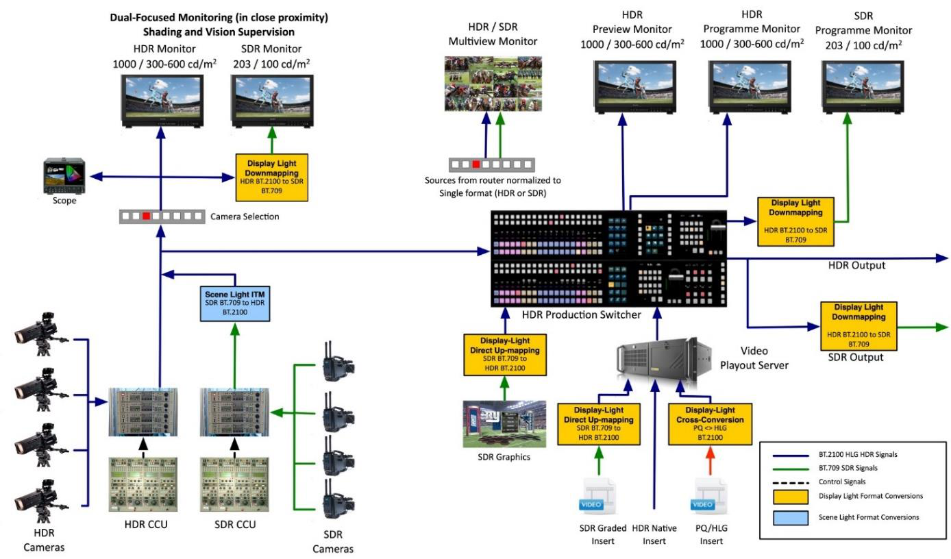
FIGURE 22 — Single-master HDR production with a dual-focused workflow
图 22. 采用双重心工作流的单母版 HDR 制作。
A variation of this approach is shown as an example in Annex 10.
这一做法的一种变体作为示例见附件 10。
7.5 Downstream distribution of a single-master production
7.5 单母版制作的下游分发
Events which use single-master HDR production techniques and are distributed in multiple regions, may provide a “World” (clean) feed in HDR and/or SDR. They can then be used in third party downstream production and/or downstream distribution, where these production and distribution methods are described as:
采用单母版 HDR 制作技术、并在多个地区分发的赛事,可提供 HDR 和/或 SDR 的“世界”(净)信号。这些信号随后可用于第三方的下游制作和/或下游分发,这两种方式描述如下:
• Downstream production: Individual, regional broadcasters can then undertake a further production to create the final programme which is sent to viewers. (For example, for sports events, they may add a studio feed of discussion before and after the game, or pitch side interviews to the World feed.) This Downstream production may also be a single-master HDR production. In this case, knowledge of the video processing and conversion undertaken by the Host broadcaster is required for a proper match or, where this is not practical (e.g. the processing is undertaken for an entire broadcast channel) to adapt the signal to best maintain the Host broadcaster’s artistic intent.
- 下游制作:各地区广播机构随后可进行二次制作,做出最终发送给观众的节目。(例如,对体育赛事,它们可能在“世界”信号上叠加赛前赛后演播室讨论的馈送,或场边采访。)这一下游制作本身也可以是单母版 HDR 制作。这种情况下,需要了解主办广播机构所做的视频处理和转换以实现恰当匹配;若这不可行(例如该处理是针对整条播出频道进行的),则需调整信号,以尽量保持主办广播机构的艺术意图。
• Downstream distribution: Where a third party takes the main HDR distribution feed and creates its own localised SDR channel variants from the HDR delivered feed either in the transmission encoder or using a local down-mapping method for HDR to SDR conversion. In this case, knowledge of the video processing undertaken by the Host production is required to either match their processing or, where this is not practical (e.g. the processing is undertaken for an entire broadcast channel) to adapt the signal to best maintain the Host broadcaster’s artistic intent.
- 下游分发:第三方接收主 HDR 分发信号,并从所交付的 HDR 信号中,或在发射端编码器内、或用本地的 HDR 到 SDR 下映射方法,做出本地化的 SDR 频道变体。这种情况下,需要了解主办制作所做的视频处理,以便匹配其处理;若这不可行(例如该处理是针对整条播出频道进行的),则需调整信号,以尽量保持主办广播机构的艺术意图。
7.6 SDR-HDR and HDR-SDR format conversion
7.6 SDR-HDR 与 HDR-SDR 格式转换
This section consists of a summary of the format conversions in §§ 7.2 and 7.3. The final choice of conversion will, however, be dependent on the producer’s intent.
本节是对 7.2 节和 7.3 节中格式转换的汇总。不过,转换的最终选择仍取决于制作方的意图。
7.6.1 PQ conversion
7.6.1 PQ 的转换
Table 8 illustrates the format conversions for PQ production.
表 8 列出 PQ 制作的格式转换。
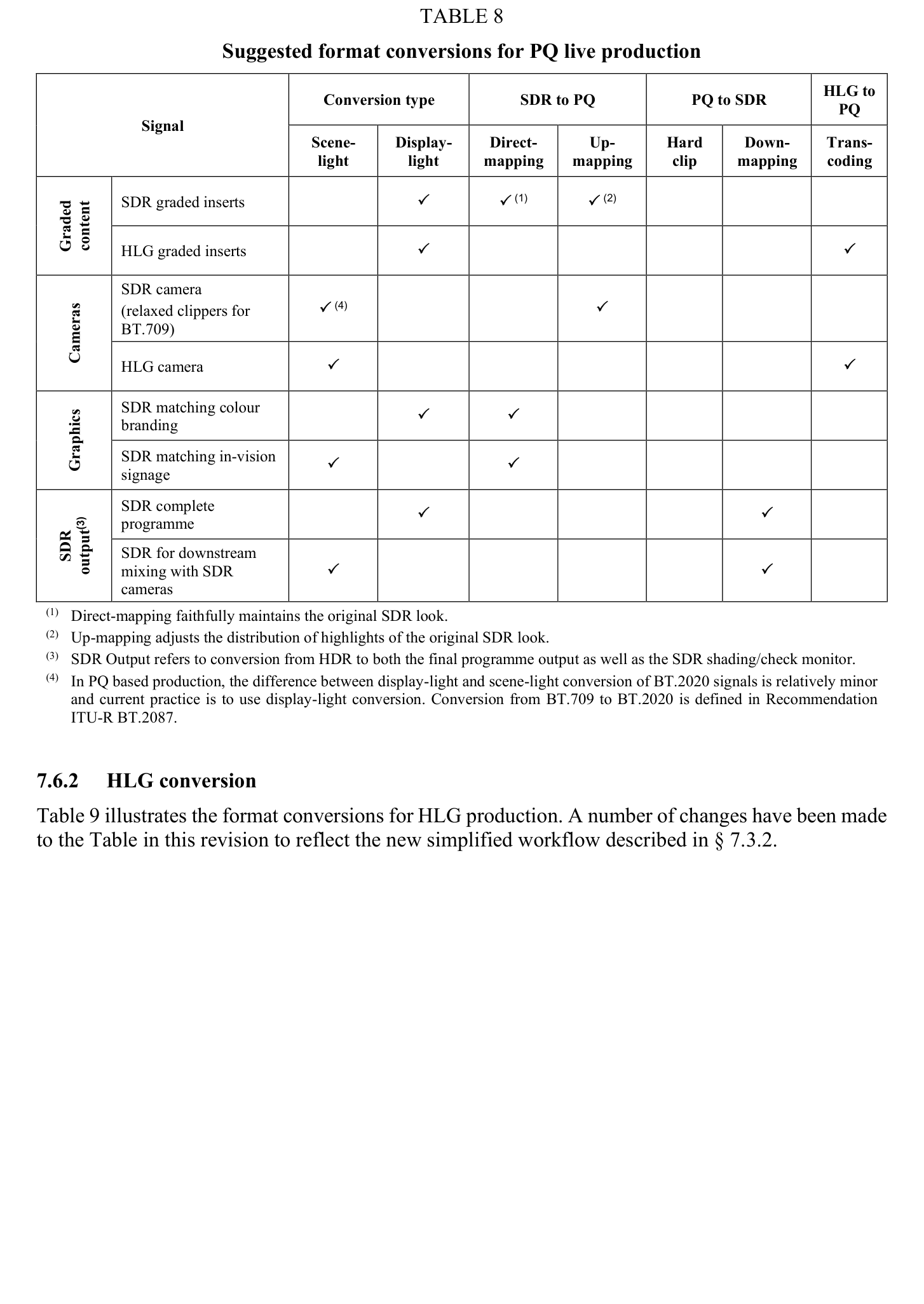
TABLE 8 — Suggested format conversions for PQ live production
表 8. PQ 直播制作建议的格式转换。(图中表格列:信号;转换类型——SDR 到 PQ:场景光 / 显示光 / 直接映射 / 上映射;PQ 到 SDR:硬削波 / 下映射;HLG 到 PQ:转码。行分为已调色内容、相机、图形、SDR 输出等。)
(1) Direct-mapping faithfully maintains the original SDR look.
(2) Up-mapping adjusts the distribution of highlights of the original SDR look.
(3) SDR Output refers to conversion from HDR to both the final programme output as well as the SDR shading/check monitor.
(4) In PQ based production, the difference between display-light and scene-light conversion of BT.2020 signals is relatively minor and current practice is to use display-light conversion. Conversion from BT.709 to BT.2020 is defined in Recommendation ITU-R BT.2087.
注⑴:直接映射忠实保持原始 SDR 观感。
注⑵:上映射会调整原始 SDR 观感中高光的分布。
注⑶:“SDR 输出”既指由 HDR 转换得到最终节目输出,也指转换给 SDR 明暗控制/检查监视器。
注⑷:在基于 PQ 的制作中,BT.2020 信号的显示光转换与场景光转换差异相对较小,目前的做法是采用显示光转换。BT.709 到 BT.2020 的转换在建议书 ITU-R BT.2087 中定义。
7.6.2 HLG conversion
7.6.2 HLG 的转换
Table 9 illustrates the format conversions for HLG production. A number of changes have been made to the Table in this revision to reflect the new simplified workflow described in § 7.3.2.
表 9 列出 HLG 制作的格式转换。本次修订对该表作了若干改动,以反映 7.3.2 节所述的新简化工作流。
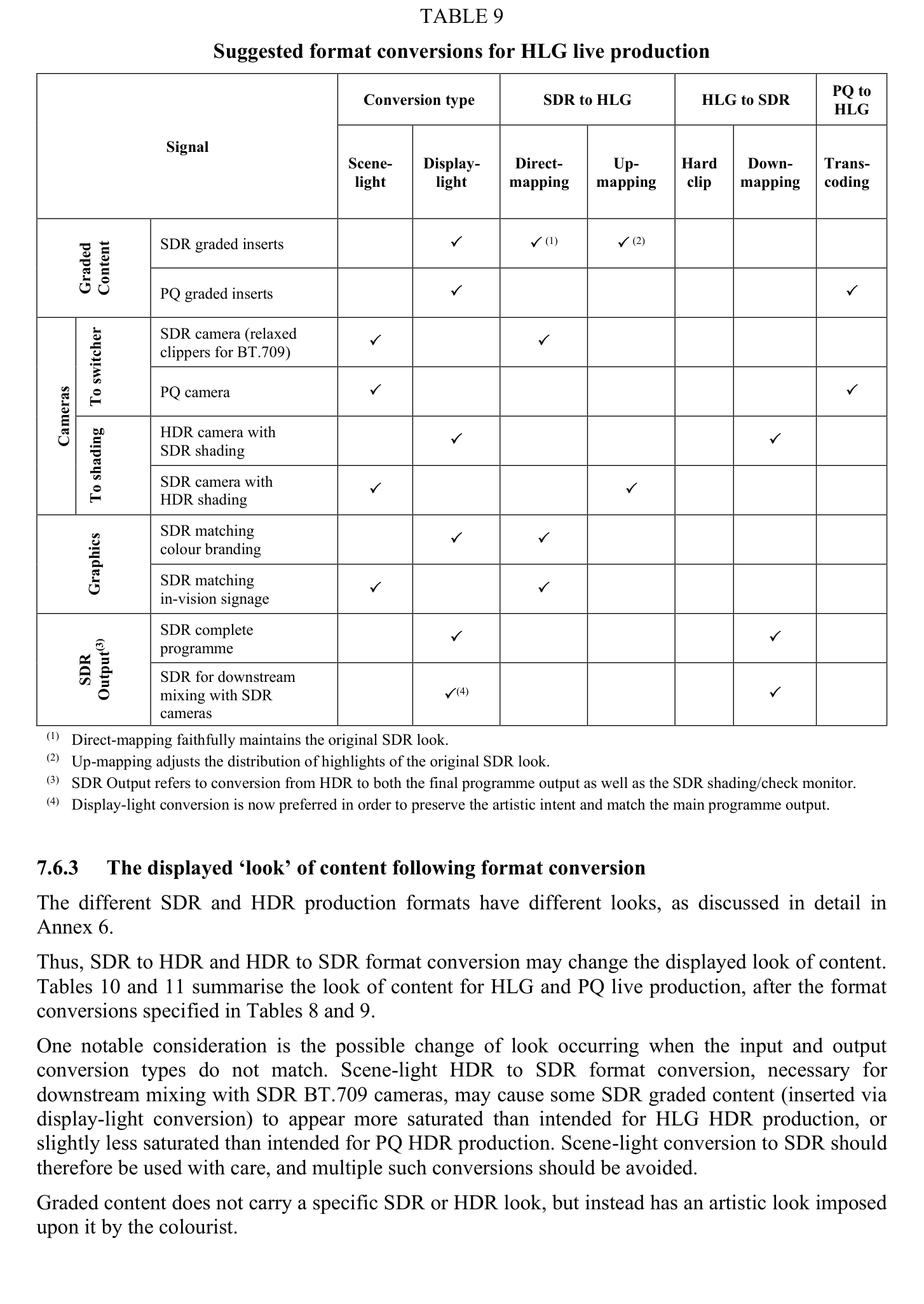
TABLE 9 — Suggested format conversions for HLG live production
表 9. HLG 直播制作建议的格式转换。(图中表格列:信号;转换类型——SDR 到 HLG:场景光 / 显示光 / 直接映射 / 上映射;HLG 到 SDR:硬削波 / 下映射;PQ 到 HLG:转码。)
(1) Direct-mapping faithfully maintains the original SDR look.
(2) Up-mapping adjusts the distribution of highlights of the original SDR look.
(3) SDR Output refers to conversion from HDR to both the final programme output as well as the SDR shading/check monitor.
(4) Display-light conversion is now preferred in order to preserve the artistic intent and match the main programme output.
注⑴:直接映射忠实保持原始 SDR 观感。
注⑵:上映射会调整原始 SDR 观感中高光的分布。
注⑶:“SDR 输出”既指由 HDR 转换得到最终节目输出,也指转换给 SDR 明暗控制/检查监视器。
注⑷:现在更倾向于采用显示光转换,以保留艺术意图并与主节目输出相匹配。
7.6.3 The displayed ‘look’ of content following format conversion
7.6.3 格式转换后内容所显示的“观感”
The different SDR and HDR production formats have different looks, as discussed in detail in Annex 6.
不同的 SDR 与 HDR 制作格式具有不同的观感,详见附件 6 的讨论。
Thus, SDR to HDR and HDR to SDR format conversion may change the displayed look of content. Tables 10 and 11 summarise the look of content for HLG and PQ live production, after the format conversions specified in Tables 8 and 9.
因此,SDR 到 HDR 以及 HDR 到 SDR 的格式转换,可能改变内容所显示的观感。表 10 和表 11 汇总了 HLG 与 PQ 直播制作经表 8、表 9 所列格式转换之后内容的观感。
One notable consideration is the possible change of look occurring when the input and output conversion types do not match. Scene-light HDR to SDR format conversion, necessary for downstream mixing with SDR BT.709 cameras, may cause some SDR graded content (inserted via display-light conversion) to appear more saturated than intended for HLG HDR production, or slightly less saturated than intended for PQ HDR production. Scene-light conversion to SDR should therefore be used with care, and multiple such conversions should be avoided.
一个值得注意的考虑是:当输入与输出的转换类型不匹配时,观感可能发生变化。场景光 HDR 到 SDR 格式转换(在下游与 SDR BT.709 相机混合时所必需)可能使某些(经显示光转换插入的)SDR 已调色内容,在 HLG HDR 制作中显得比预期更饱和,或在 PQ HDR 制作中显得比预期略欠饱和。因此,向 SDR 的场景光转换应谨慎使用,并应避免多次进行这类转换。
Graded content does not carry a specific SDR or HDR look, but instead has an artistic look imposed upon it by the colourist.
已调色内容并不带有特定的 SDR 或 HDR 观感,而是带有调色师赋予它的艺术观感。
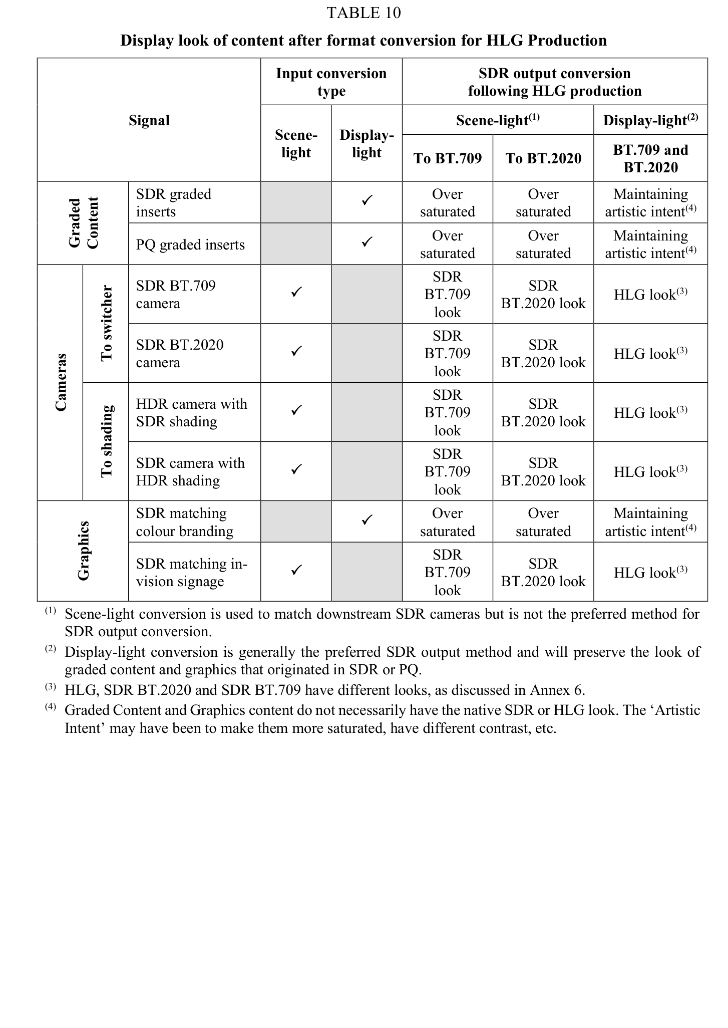
TABLE 10 — Display look of content after format conversion for HLG Production
表 10. HLG 制作中内容经格式转换后的显示观感。(列:信号;输入转换类型——场景光 / 显示光;HLG 制作后的 SDR 输出转换——场景光〔到 BT.709 / 到 BT.2020〕、显示光〔BT.709 与 BT.2020〕。单元格观感如“过饱和”“SDR BT.709 观感”“SDR BT.2020 观感”“保持艺术意图”“HLG 观感”等。)
(1) Scene-light conversion is used to match downstream SDR cameras but is not the preferred method for SDR output conversion.
(2) Display-light conversion is generally the preferred SDR output method and will preserve the look of graded content and graphics that originated in SDR or PQ.
(3) HLG, SDR BT.2020 and SDR BT.709 have different looks, as discussed in Annex 6.
(4) Graded Content and Graphics content do not necessarily have the native SDR or HLG look. The ‘Artistic Intent’ may have been to make them more saturated, have different contrast, etc.
注⑴:场景光转换用于匹配下游 SDR 相机,但并非 SDR 输出转换的优选方法。
注⑵:显示光转换通常是优选的 SDR 输出方法,能保留源自 SDR 或 PQ 的已调色内容和图形的观感。
注⑶:HLG、SDR BT.2020 与 SDR BT.709 具有不同的观感,见附件 6 的讨论。
注⑷:已调色内容和图形内容未必具有原生的 SDR 或 HLG 观感。其“艺术意图”可能本就是让它们更饱和、具有不同对比度等。
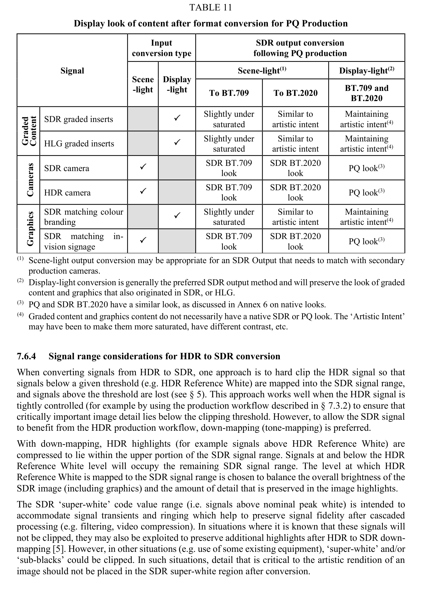
TABLE 11 — Display look of content after format conversion for PQ Production
表 11. PQ 制作中内容经格式转换后的显示观感。(列:信号;输入转换类型——场景光 / 显示光;PQ 制作后的 SDR 输出转换——场景光〔到 BT.709 / 到 BT.2020〕、显示光〔BT.709 与 BT.2020〕。单元格观感如“略欠饱和”“与艺术意图相近”“保持艺术意图”“SDR BT.709 观感”“SDR BT.2020 观感”“PQ 观感”等。)
(1) Scene-light output conversion may be appropriate for an SDR Output that needs to match with secondary production cameras.
(2) Display-light conversion is generally the preferred SDR output method and will preserve the look of graded content and graphics that also originated in SDR, or HLG.
(3) PQ and SDR BT.2020 have a similar look, as discussed in Annex 6 on native looks.
(4) Graded content and graphics content do not necessarily have a native SDR or PQ look. The ‘Artistic Intent’ may have been to make them more saturated, have different contrast, etc.
注⑴:场景光输出转换可能适用于需要与二级制作相机匹配的 SDR 输出。
注⑵:显示光转换通常是优选的 SDR 输出方法,能保留同样源自 SDR 或 HLG 的已调色内容和图形的观感。
注⑶:PQ 与 SDR BT.2020 具有相近的观感,见附件 6 关于原生观感的讨论。
注⑷:已调色内容和图形内容未必具有原生的 SDR 或 PQ 观感。其“艺术意图”可能本就是让它们更饱和、具有不同对比度等。
7.6.4 Signal range considerations for HDR to SDR conversion
7.6.4 HDR 到 SDR 转换的信号范围考虑
When converting signals from HDR to SDR, one approach is to hard clip the HDR signal so that signals below a given threshold (e.g. HDR Reference White) are mapped into the SDR signal range, and signals above the threshold are lost (see § 5). This approach works well when the HDR signal is tightly controlled (for example by using the production workflow described in § 7.3.2) to ensure that critically important image detail lies below the clipping threshold. However, to allow the SDR signal to benefit from the HDR production workflow, down-mapping (tone-mapping) is preferred.
把信号从 HDR 转换为 SDR 时,一种做法是对 HDR 信号作硬削波,使低于某给定阈值(如 HDR 参考白)的信号映射进 SDR 信号范围,而高于该阈值的信号则丢失(见第 5 节)。当 HDR 信号受到严格控制(例如采用 7.3.2 节所述的制作工作流)以确保至关重要的图像细节都落在削波阈值以下时,这种做法效果良好。不过,为让 SDR 信号也从 HDR 制作工作流中获益,更倾向于采用下映射(色调映射)。
With down-mapping, HDR highlights (for example signals above HDR Reference White) are compressed to lie within the upper portion of the SDR signal range. Signals at and below the HDR Reference White level will occupy the remaining SDR signal range. The level at which HDR Reference White is mapped to the SDR signal range is chosen to balance the overall brightness of the SDR image (including graphics) and the amount of detail that is preserved in the image highlights.
采用下映射时,HDR 高光(例如高于 HDR 参考白的信号)被压缩到 SDR 信号范围的高段之内。处于及低于 HDR 参考白电平的信号则占据余下的 SDR 信号范围。HDR 参考白映射到 SDR 信号范围所处的电平,是为在 SDR 图像(含图形)的整体亮度与图像高光中所保留细节量之间取得平衡而选定的。
The SDR ‘super-white’ code value range (i.e. signals above nominal peak white) is intended to accommodate signal transients and ringing which help to preserve signal fidelity after cascaded processing (e.g. filtering, video compression). In situations where it is known that these signals will not be clipped, they may also be exploited to preserve additional highlights after HDR to SDR down-mapping [5]. However, in other situations (e.g. use of some existing equipment), ‘super-white’ and/or ‘sub-blacks’ could be clipped. In such situations, detail that is critical to the artistic rendition of an image should not be placed in the SDR super-white region after conversion.
SDR“超白”码值范围(即高于标称峰值白的信号)本是用来容纳信号瞬变和振铃的,它们有助于在级联处理(如滤波、视频压缩)后保持信号保真度。在已知这些信号不会被削掉的情况下,也可利用它们在 HDR 到 SDR 下映射后保留额外的高光 [5]。但在其他情况下(如使用某些现有设备),“超白”和/或“次黑”可能被削掉。在这种情况下,对图像艺术呈现至关重要的细节,转换后不应放在 SDR 超白区域中。
7.7 SDR-HDR-SDR ‘Round-Tripping’
7.7 SDR-HDR-SDR “往返转换”
As described in § 7.2, SDR signals will be converted to HDR during production and back again to SDR for distribution. This is the process known as ‘round-tripping’.
如 7.2 节所述,SDR 信号在制作中会被转换为 HDR,再为分发转换回 SDR。这一过程即所谓的“往返转换”。
Ideally, the process of round-tripping would be transparent. However, in practice, this is difficult to achieve and is the subject of on-going investigation. To understand the difficulties that can arise it is helpful to consider the individual processes of up-mapping to HDR and down-mapping to SDR. There are two main approaches to including SDR content in HDR programmes: direct-mapping and up-mapping (more information in § 5).
理想情况下,往返转换过程应当是透明无损的。但实践中这很难做到,仍是持续研究的课题。要理解其中可能出现的困难,不妨分别考察上映射到 HDR 和下映射到 SDR 这两个过程。在 HDR 节目中纳入 SDR 内容主要有两种做法:直接映射和上映射(详见第 5 节)。
Conversion from HDR to SDR is also considered in § 5, where again two approaches are described: hard clipping, where the conversion can be regarded as a direct-mapping of HDR onto an SDR display, and down-mapping. In down-mapping, the HDR to SDR conversion uses a non-linearity, similar (and analogous) to the ‘knee’ function found in cameras. This non-linear mapping reduces the dynamic range of highlights but does not completely remove them.
第 5 节也讨论了从 HDR 到 SDR 的转换,同样描述了两种做法:硬削波(此时转换可看作把 HDR 直接映射到 SDR 显示设备上)和下映射。下映射中,HDR 到 SDR 转换使用一个非线性变换,类似于(也对应于)相机中的“拐点”函数。这一非线性映射会缩小高光的动态范围,但不会把高光完全去掉。
In both up-mapping and down-mapping, careful attention should be paid to those ‘diffuse’ parts of the scene that can be supported in both SDR and HDR formats. However, this is made difficult by variation of the scene luminance factor corresponding to reference white (100%SDR signal) in SDR productions. SDR signals provide little ‘headroom’ for highlights. Some SDR signals are simply clipped of most of the highlight information (e.g. live sport), but in other cases include more highlights through the use of a camera ‘knee’ (e.g. drama or sport ‘beauty’ shots).
无论上映射还是下映射,都应仔细关注场景中那些 SDR 与 HDR 两种格式都能支持的“漫反射”部分。然而,SDR 制作中对应参考白(100% SDR 信号)的场景亮度因数各不相同,这给上述工作带来了困难。SDR 信号为高光留出的“余量”很少:有些 SDR 信号干脆把大部分高光信息削掉(如体育直播),但另一些则通过使用相机“拐点”纳入更多高光(如剧情片或体育节目的“唯美”镜头)。
The optimum techniques for up-mapping followed by down-mapping are still under investigation. However, in live production where SDR camera sources are often heavily ‘clipped’ direct-mapping of SDR into HDR (i.e. with no expansion of image highlights) is usually preferred. In order to minimise ‘round-trip’ losses after direct-mapping, the HDR to SDR down-mappers used in live production increasingly place the HDR image highlights within the SDR ‘super-white’ signal range; thereby allowing HDR Reference White to be mapped to ~95% SDR signal, whilst still preserving some compressed HDR image highlights.
先上映射、后下映射的最佳技术仍在研究之中。不过,在 SDR 相机源常被大幅“削波”的直播制作中,通常更倾向于把 SDR 直接映射进 HDR(即不扩展图像高光)。为在直接映射后尽量减少“往返”损失,直播制作所用的 HDR 到 SDR 下映射器越来越多地把 HDR 图像高光放进 SDR“超白”信号范围,从而让 HDR 参考白映射到约 95% 的 SDR 信号,同时仍保留一些压缩后的 HDR 图像高光。
7.8 Hardware colour matrix compensation
7.8 硬件色彩矩阵补偿
Many of the existing hardware devices assume BT.709 colorimetry when converting between R′G′B′ and Y′C′BC′R signal formats.
许多现有硬件设备在 R′G′B′ 与 Y′C′BC′R 信号格式之间转换时,都假定采用 BT.709 色度学。
Where it is not possible to configure a device for BT.2100 colorimetry, a correction needs to be applied elsewhere. This might be in the conversion matrix on the complementary interface at the other end of the link (e.g. within a display) or, as illustrated in Fig. 23, within a look-up table performing a format conversion.
当无法把某设备配置为 BT.2100 色度学时,就需要在别处施加修正。修正之处可以是链路另一端互补接口上的转换矩阵(例如在显示设备内),也可以如图 23 所示,在执行格式转换的查找表内。
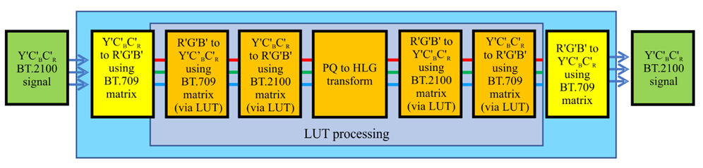
FIGURE 23 — Example of colour matrix compensation within a LUT
图 23. 在 LUT 内进行色彩矩阵补偿的示例。
7.9 Signal line-up
7.9 信号校线
Prior to any live transmission, it is common practice for broadcasters to check the end-to-end integrity of the production and contribution signal chain. Typically, a signal generator producing colour bars and a lipsync test is fed into the production switcher or matrix. The video waveform and lipsync is then checked for accuracy at various points along the chain, including the broadcaster’s MCR (Master Control Room).
在任何直播发射之前,广播机构通常会检查制作链和汇接链信号通路端到端的完整性。典型做法是把一台产生彩条和唇音同步测试信号的信号发生器,馈入制作切换台或矩阵,然后在链路沿途的各点(包括广播机构的总控室 MCR)检查视频波形和唇音同步的准确性。
If BT.2111 Colour Bars are used as the signal source, after any HDR to SDR conversion (e.g. to feed an SDR contribution circuit) the wide colour gamut bars within the test pattern should not be expected to land on the colour bar targets of a standard BT.709 vectorscope; as the SDR BT.709 and HDR BT.2100 colour primaries are different, the true displayed colours of the respective primary (red, green, blue) and secondary (yellow, cyan, magenta) colour bar signals are also different. The BT.709 (scene light) colour bars within the BT.2111 test pattern may also not land on the colour bar targets after scene light down-mapping, as their luminance could be affected by any tone-mapping from HDR to SDR. They should not be expected to land on the colour bar targets after display light down-mapping.
如果用 BT.2111 彩条作为信号源,则在任何 HDR 到 SDR 转换之后(例如为馈送 SDR 汇接电路),不应指望测试图案中的宽色域彩条会落在标准 BT.709 矢量示波器的彩条靶标上;因为 SDR BT.709 与 HDR BT.2100 的基色不同,各基色(红、绿、蓝)和间色(黄、青、品红)彩条信号真正显示出的色彩也不同。BT.2111 测试图案中的 BT.709(场景光)彩条,在经场景光下映射后也可能不落在彩条靶标上,因为其亮度可能受 HDR 到 SDR 任何色调映射的影响;它们在经显示光下映射后也不应指望落在彩条靶标上。
Work is currently underway to design test patterns for signal line-up that should provide a predictable output after display-light and scene-light HDR to SDR conversion.
目前正在研究设计用于信号校线的测试图案,使其在经显示光和场景光 HDR 到 SDR 转换后能给出可预期的输出。
7.10 Camera painting
7.10 摄像机调校(painting)
Different programmes genres often require different ‘looks’. The look that audiences expect for a particular genre may even vary between regions. A television drama, often shot on large format single sensor cameras in a ‘RAW’ format, for example, might be graded to give a look which is of an artistic nature and with colours subdued, and perhaps with less contrast too. A live sporting event such as football produced with multi sensor cameras, might be produced with images that are a little more colourful than nature and may have additional mid-tone contrast added within the CCU to deliver a ‘punchy’ eye-catching look.
不同的节目类型往往需要不同的“观感”。观众对某一类型所期待的观感,甚至可能因地区而异。例如,电视剧常用大画幅单传感器相机以“RAW”格式拍摄,可能经调色后呈现出偏艺术、色彩较收敛、或许对比度也较低的观感。而像足球这样用多传感器相机制作的体育赛事直播,所做出的图像可能比自然界略微鲜艳,并可能在摄像机控制单元(CCU)内额外增加中间调对比度,以呈现“有冲击力”、抓人眼球的观感。
Each production format has its own native look, determined by the OOTF. The looks vary in colour saturation and mid-tone contrast. A comparison of the native looks of HDR and SDR production formats is given in Annex 6. The native look of any given format may not necessarily match the expected look of a particular programme genre, nor the aesthetic that the programme maker wishes to achieve. Non-live programmes will, therefore, often need to be colour graded offline, and live HDR cameras will usually need to be ‘painted’ in real-time.
每种制作格式都有自己的原生观感,由 OOTF 决定。各种观感在色彩饱和度和中间调对比度上各不相同。HDR 与 SDR 制作格式原生观感的比较见附件 6。任何给定格式的原生观感,未必与某一节目类型所期待的观感相符,也未必与节目制作者想要达到的美学相符。因此,非直播节目往往需要离线调色,直播 HDR 相机则通常需要实时“调校(painting)”。
Annex 6 illustrates how HLG has been designed to deliver a look that preserves the chromaticity of the scene as imaged by the camera. SDR BT.709, BT.2020 and the PQ production formats provide a more colourful look. Moreover, although the OOTF ‘gammas’ of all four formats in the reference viewing environment are similar, approximately 1.2, the subjective mid-tone contrast of a BT.709 image shown on a reference display in the reference viewing environment is greater than that of either PQ or HLG.
附件 6 说明 HLG 是如何被设计成提供一种保留相机所成场景色品的观感的。SDR BT.709、BT.2020 和 PQ 制作格式则提供更鲜艳的观感。此外,尽管四种格式在参考观看环境下的 OOTF“伽马”都相近(约为 1.2),但在参考观看环境中、参考显示设备上呈现的 BT.709 图像,其主观中间调对比度高于 PQ 或 HLG。
The difference in perceived mid-tone contrast arises because of the difference in the diffuse white level of an SDR image (
100 cd/m2) and that of an HDR image (200 cd/m2). As the HDR image is brighter, and the OOTF gammas are the same, when viewed in isolation the detail in the shadows of the HDR image will be more visible than in the SDR image and the mid-tones will also appear subjectively brighter. Furthermore, the BT.709 and BT.2020 OETFs have a linear portion near black, originally intended to reduce the visibility of camera sensor noise. That linear portion in the SDR OETFs also serves to further increase the perceived mid-tone contrast as it compresses detail towards the shadows. The linear portion, however, resulted in less accurate quantization of the low-light levels and so was omitted from the HLG OETF as cameras now employ more sophisticated noise reduction techniques.
感知中间调对比度的差异,源于 SDR 图像漫反射白电平(约 100 cd/m²)与 HDR 图像漫反射白电平(约 200 cd/m²)的不同。由于 HDR 图像更亮、而 OOTF 伽马相同,单独观看时 HDR 图像暗部的细节会比 SDR 图像更可见,中间调在主观上也显得更亮。此外,BT.709 和 BT.2020 的 OETF 在接近黑处有一段线性区,本意是降低相机传感器噪声的可见性。SDR OETF 中的这段线性区还会进一步提高感知中间调对比度,因为它把细节朝暗部压缩。不过,这段线性区导致低光电平的量化不够准确,因此随着相机如今采用更先进的降噪技术,HLG OETF 便省去了它。
Therefore, it is important when producing certain types of live (or as-live) content that HLG (and to a lesser extent PQ) cameras may be beneficially ‘painted’ to produce a ‘punchy’ and colourful look when intended by programme producers and expected by audiences.
因此,在制作某些类型的直播(或准直播)内容时,一个要点是:当节目制作者有意、观众也有此期待时,对 HLG 相机(PQ 相机程度稍轻)作“调校”以产生“有冲击力”、鲜艳的观感,可能是有益的。
7.11 Progressive-to-interlaced conversion
7.11 逐行到隔行的转换
7.11.1 Filtering for progressive-to-interlaced conversion
7.11.1 逐行到隔行转换的滤波
When converting progressive content for interlaced distribution, it is essential to use a converter with appropriate filtering to minimise interlace ‘twitter’, which is an aliasing artefact that may be difficult to remove by the de-interlacing process in the display.
把逐行内容转换以用于隔行分发时,必须使用带适当滤波的转换器,以尽量减少隔行“行间闪烁(twitter)”——这是一种混叠伪影,显示设备中的去隔行过程可能很难将其去除。
Interlacing is a form of down-sampling in both vertical space and time, so a vertical-temporal filter, i.e. a filter that includes frame buffering, may give the best subjective results for a particular application. Pure vertical filters can also be used as an alternative when minimising delay is important.
隔行是垂直空间和时间两方面的一种下采样,因此对某一特定应用而言,垂直-时间滤波器(即包含帧缓冲的滤波器)可能给出最佳的主观效果。当尽量减小延迟很重要时,也可改用纯垂直滤波器。
Figure 24 shows progressive and interlaced sampling structures in the frequency domain, and two possible interlacing filter shapes. The vertical-temporal filter illustrated in Fig. 24 (e) and (f) achieves a higher vertical resolution for stationary objects than the pure vertical filter of Fig. 24 (c) and (d), at the expense of reduced resolution for moving objects. Further, a motion-adaptive filter switching between a pure vertical filter and a vertical-temporal filter has the potential to provide a subjectively better result in resolution.
图 24 给出频域中的逐行和隔行采样结构,以及两种可能的隔行滤波器形状。图 24(e)和(f)所示的垂直-时间滤波器,对静止物体能获得比图 24(c)和(d)的纯垂直滤波器更高的垂直分辨率,代价是运动物体的分辨率降低。此外,在纯垂直滤波器与垂直-时间滤波器之间切换的运动自适应滤波器,有望在分辨率上提供主观更佳的结果。
A description of interlacing principles and a comparison of a selection of filters is presented in BBC R&D White Paper 315 [6], specifically for 1080p50 to 1080i25 conversion. Subjective testing has shown that the exact filter aperture is not critical, so the conclusions are likely to be broadly applicable to 60 Hz systems as well, but testing is recommended.
BBC 研发白皮书 315 [6] 介绍了隔行原理,并比较了一组所选滤波器,专门针对 1080p50 到 1080i25 的转换。主观测试表明滤波器的具体孔径并不关键,因此这些结论很可能也大体适用于 60 Hz 系统,但仍建议进行测试。
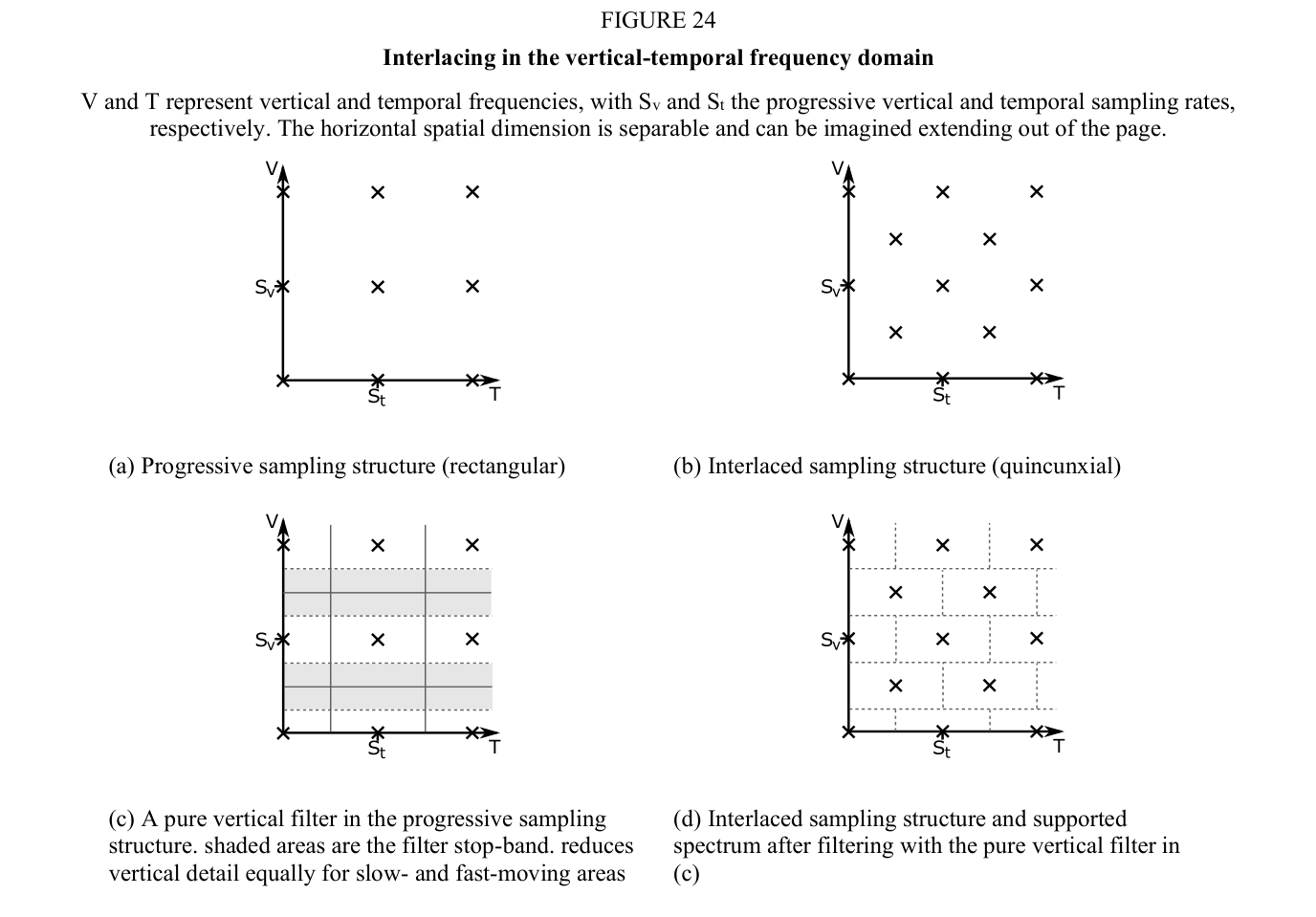
FIGURE 24 — Interlacing in the vertical-temporal frequency domain. V and T represent vertical and temporal frequencies, with Sv and St the progressive vertical and temporal sampling rates, respectively. The horizontal spatial dimension is separable and can be imagined extending out of the page.
图 24. 垂直-时间频域中的隔行。 V 和 T 代表垂直频率和时间频率,S_v 和 S_t 分别为逐行的垂直采样率和时间采样率。水平空间维度可分离,可设想其垂直于纸面向外延伸。(a)逐行采样结构(矩形);(b)隔行采样结构(梅花形);(c)逐行采样结构中的纯垂直滤波器,阴影区为滤波器阻带,对慢速和快速运动区域同等地降低垂直细节;(d)用(c)的纯垂直滤波器滤波后的隔行采样结构及所支持的频谱;(e)逐行采样结构中的一个垂直-时间滤波器示例,阴影区为滤波器阻带,对快速运动区域比对慢速运动区域更多地降低垂直细节;(f)用(e)的垂直-时间滤波器滤波后的隔行采样结构及所支持的频谱。
7.11.2 Issues with progressive to interlace workflows
7.11.2 逐行到隔行工作流的若干问题
Two workflows are currently used to convert live UHD HDR produced content to an HD SDR interlaced feed for distribution:
– Conversion from 2160p HDR to 1080i SDR within one piece of equipment.
– Two-stage conversion from 2160p HDR to 1080p HDR and then to 1080i SDR, at separate points in the workflow.
目前有两种工作流用于把直播 UHD HDR 制作内容转换为用于分发的 HD SDR 隔行馈送:
- 在单台设备内从 2160p HDR 转换到 1080i SDR;
- 分两阶段、在工作流中不同位置先从 2160p HDR 转换到 1080p HDR、再转换到 1080i SDR[5]。
When using the first method, care should be taken in tuning the filtering to ensure a visually pleasing trade-off between sharpness, aliasing and ringing whilst ensuring that any further processing or encoding is not affected.
采用第一种方法时,应注意调好滤波,在锐度、混叠和振铃之间取得视觉上令人满意的折中,同时确保不影响任何后续处理或编码。
When using the second method, the scaling and interlacing stages can either be undertaken by a single broadcaster or, commonly for major events, a host broadcaster may provide a 1080p HDR feed which is then converted to 1080i SDR by a local broadcaster for onwards distribution.
采用第二种方法时,缩放和隔行两个阶段既可由单一广播机构完成;对重大赛事,也常见主办广播机构提供 1080p HDR 馈送,再由本地广播机构转换为 1080i SDR 以继续分发。
Both theoretical and experimental results show that it is possible to adjust the scaling filter to create a visually pleasing 1080p HDR video stream with significant high frequency content which cannot then be converted to 1080i SDR without creating significant visual artefacts [7]. The filtering in the scaling stage is able to pass significantly more detail than the modulation transfer function of a 1080p camera system would. When broadcasters are creating a 1080p HDR stream designed for further processing and distribution by third parties, it is advisable to check that the 1080p stream can be interlaced without significant visual artefacts being present.
理论和实验结果都表明:有可能把缩放滤波器调成做出一条视觉上令人满意、含大量高频成分的 1080p HDR 视频流,而这条视频流随后无法在不产生明显视觉伪影的情况下转换为 1080i SDR [7]。缩放阶段的滤波所能通过的细节,明显多于 1080p 相机系统的调制传递函数所能通过的。当广播机构制作一条供第三方进一步处理和分发的 1080p HDR 流时,宜检查该 1080p 流能否在不出现明显视觉伪影的情况下进行隔行。
When a camera with a 1080p HDR sensor is used, these issues are less evident as they capture similar detail levels to a 1080p SDR sensor.
使用带 1080p HDR 传感器的相机时,这些问题不那么明显,因为它们所采集的细节量与 1080p SDR 传感器相近。
7.12 Look-up Table (LUT) conversions in HDR television production
7.12 HDR 电视制作中的查找表(LUT)转换
Look-up Table conversions are used widely in HDR television production to convert between video formats. Examples include conversions between SDR BT.709 or BT.2020 and HDR BT.2100 (PQ or HLG), and between PQ and HLG.
查找表转换在 HDR 电视制作中被广泛用于在各视频格式之间转换。例如 SDR BT.709 或 BT.2020 与 HDR BT.2100(PQ 或 HLG)之间、以及 PQ 与 HLG 之间的转换。
Correct operation requires knowledge of the format of the input and output video signals. Additionally, there is currently no standardized nomenclature for look-up table conversion controls and their settings to achieve the desired operation. This can sometimes lead to confusion when LUT conversions are in use from multiple vendors with differing naming conventions.
要正确操作,须了解输入和输出视频信号的格式。此外,目前对于实现所需操作的查找表转换控制项及其设置,尚无标准化的命名。当同时使用多家厂商、命名约定各异的 LUT 转换时,这有时会引起混淆。
Examples of basic LUT conversion controls and typical settings with nomenclature are shown in Table 12.
基本 LUT 转换控制项及其典型设置和命名的示例见表 12。
表 12. LUT 转换控制项与命名
| 控制项名称 | 设置 |
|---|---|
| 输入矩阵系数⁽¹⁾ | BT.709,BT.2020/BT.2100 |
| 输入信号范围 | 窄/全 |
| 输入处理范围 | 标称/扩展⁽³⁾ |
| 输出矩阵系数⁽²⁾ | BT.709,BT.2020/BT.2100 |
| 输出转换特性 | BT.709,BT.2020,BT.2100 HLG,BT.2100 PQ |
| 输出信号范围 | 窄/全 |
| 输出处理范围 | 标称/扩展⁽³⁾ |
(1) For colour space conversion from Y’C’BC’R to R’G’B’.
(2) For colour space conversion from R’G’B’ to Y’C’BC’R.
(3) Includes the processing of sub-blacks and super-whites.
注⑴:用于从 Y′C′BC′R 到 R′G′B′ 的色彩空间转换。
注⑵:用于从 R′G′B′ 到 Y′C′BC′R 的色彩空间转换。
注⑶:包括对次黑和超白的处理。
Common naming of LUT conversion controls and settings would help avoid misunderstandings and facilitate easier installation and setup.
对 LUT 转换控制项和设置采用统一命名,将有助于避免误解,并使安装和设置更为简便。
7.13 Floating-point signal representation for programme exchange
7.13 用于节目交换的浮点信号表示
Recommendation ITU-R BT.2100 specifies two non-linear representations for HDR signals that allow good quality to be achieved at 10- or 12-bits, and also specifies a linear 16-bit floating-point representation. This linear representation is often used in signal processing when floating-point hardware is present and may be employed for programme exchange.
建议书 ITU-R BT.2100 为 HDR 信号规定了两种非线性表示,使其在 10 或 12 比特下即可达到良好质量;它还规定了一种线性的 16 比特浮点表示。当存在浮点硬件时,这种线性表示常用于信号处理,也可用于节目交换。
Floating-point has been employed in high quality programme production in the professional-grade image storage format of the motion picture industry, OpenEXR [8]. This format includes metadata to indicate the normalization, i.e. what display light level is represented by the floating-point value of 1.0. For SDR TV programmes compliant with Recommendation ITU-R BT.709, 1.0 generally represents 100 cd/m2. For general digital cinema releases, 1.0 would represent 48 cd/m2. For broadcast HDR content, BT.2100 specifies that 1.0 should map to reference white which is defined in Report ITU-R BT.2408 to be 203 cd/m2. The consistent normalization of reference white to 1.0 facilitates the mixing of different types of content onto a computer screen as may occur in windowed display systems.
电影业的专业级图像存储格式 OpenEXR [8] 已在高质量节目制作中采用浮点。该格式包含元数据以指明归一化方式,即浮点值 1.0 代表怎样的显示光电平。对符合建议书 ITU-R BT.709 的 SDR 电视节目,1.0 一般代表 100 cd/m²;对一般数字电影发行,1.0 代表 48 cd/m²;对广播 HDR 内容,BT.2100 规定 1.0 应映射到参考白,而报告 ITU-R BT.2408 把参考白定义为 203 cd/m²。把参考白一致地归一化为 1.0,便于在窗口式显示系统中(如在电脑屏幕上)混合不同类型的内容。
For the very highest quality, including fine resolution in deep blacks, a normalization of 1.0 (floating-point value) to 1.0 cd/m2 is sometimes employed in programme production.
为追求最高质量(包括深黑部位的精细分辨),节目制作中有时采用把 1.0(浮点值)归一化为 1.0 cd/m² 的方式。
To see why resolution is an issue to some users requires a closer look at the IEEE 754 floating-point specification. Without getting into all the details of the 16-bit format, the smallest non-zero value that can be represented is 2−14 × (0 + 1/1 024) = 5.96046 × 10⁻⁸ and the largest is 215 × (1 + 1 023/1 024) = 65 504. Code 1 in 12-bit PQ represents 3.68488 × 10⁻⁶ cd/m2 and code 4 095 represents 10 000 cd/m2. So a floating-point normalization of 1.0 cd/m2 completely contains all 12-bit PQ values with some extra precision available even at the lowest levels. But a floating-point normalization of 203 cd/m2 would set the range limits at 1.20997 × 10⁻⁵ cd/m2 and 1.32973 × 10⁷ cd/m2, having less range and lower precision than 12-bit PQ at the lowest levels. In broadcast use cases this level of precision may not be needed, and a 203 cd/m2 normalization may be used effectively.
要弄清为什么分辨率对某些用户是个问题,需要细看 IEEE 754 浮点规范。不深究 16 比特格式的全部细节:它能表示的最小非零值为 2⁻¹⁴ × (0 + 1/1024) = 5.96046 × 10⁻⁸,最大值为 2¹⁵ × (1 + 1023/1024) = 65 504。12 比特 PQ 中码值 1 代表 3.68488 × 10⁻⁶ cd/m²,码值 4 095 代表 10 000 cd/m²。因此,把浮点归一化为 1.0 cd/m²,可完整容纳全部 12 比特 PQ 值,甚至在最低电平处还有一些额外精度。但把浮点归一化为 203 cd/m²,则会把范围上下限定在 1.20997 × 10⁻⁵ cd/m² 和 1.32973 × 10⁷ cd/m²,在最低电平处其范围比 12 比特 PQ 更小、精度也更低。在广播用例中可能并不需要这种精度,因此采用 203 cd/m² 归一化也能有效使用。
For signals from cameras which are intended to be scene-referred, the floating-point value of 1.0 should be normalized to the luminance of a diffuse white object with 100% reflectance. Because cameras sometimes alter peak whites due to the use of knees or other non-linear processing, an alternative way to adjust the normalization is to use an 18% grey card and normalize the level of that to 0.18.
对来自相机、拟作场景参考的信号,浮点值 1.0 应归一化为 100% 反射率漫反射白物体的亮度。由于相机有时会因使用拐点或其他非线性处理而改变峰值白,调整归一化的另一种办法是使用 18% 灰卡,并把它的电平归一化为 0.18。
8 Conversion practices for camera and display RGB colorimetry
8 相机与显示设备 RGB 色度学的转换实践
Several camera and display systems, for both professional and consumer applications, use their own colour primaries, a practice that may give them certain advantages during capture or display respectively. However, content captured or displayed on such devices would still have to be transformed to or from a BT.2100 workflow, respectively. It should be noted that the transformations in this document only apply under the following conditions:
– The source and target white points are the same and should be equal to D65.
– The source and target white point brightness is the same. For scenarios where brightness is different, refer to Report ITU-R BT.2446.
Furthermore, these transformations are not applicable for camera RAW signals.
无论专业还是消费应用,若干相机和显示系统都使用各自的基色,这种做法可能分别在采集或显示时带来某些优势。然而,在这类设备上采集或显示的内容,仍须分别转换进或转换出 BT.2100 工作流。需要注意,本文件中的转换只在以下条件下适用:
- 源白点与目标白点相同,且应等于 D65;
- 源白点与目标白点的亮度相同。亮度不同的情形请参阅报告 ITU-R BT.2446。
此外,这些转换不适用于相机 RAW 信号。
Camera and display systems are commonly defined by their normalized primary matrix, NPM, which is specified as follows:
相机和显示系统通常由其归一化基色矩阵(NPM)来定义,规定如下:
where the elements of the matrix depend on the chromaticity coordinates, (xR, yR), (xG, yG), (xB, yB), and (xW, yW) for red, green, blue, and white, respectively, that characterize each system.
式中矩阵各元素取决于刻画各系统特征的色度坐标,即红、绿、蓝、白分别对应的 (x_R, y_R)、(x_G, y_G)、(x_B, y_B) 和 (x_W, y_W)。
The NPM is needed for the conversion process to and from the CIE XYZ colour space and the BT.2100 colour space. The specifics of the computation may be found in Annex 7.
在 CIE XYZ 色彩空间与 BT.2100 色彩空间之间相互转换的过程都需要 NPM。计算的具体细节见附件 7。
9 Graphics
9 图形
SDR graphics should be directly mapped into the HDR signal at the ‘Graphics White’ signal level specified in Table 1 (75% HLG or 58%PQ) to avoid them appearing too bright, and thus making the underlying video appear dull in comparison. Where the desire is to maintain the colour branding of the SDR graphics, a display-light mapping should be used. Where the desire is to match signage within the captured scene (in-vision signage; e.g. a score board at a sporting event), a scene-light mapping is usually preferred.
SDR 图形应按表 1 规定的“图形白”信号电平(75% HLG 或 58% PQ)直接映射进 HDR 信号,以免它们显得过亮、从而使底层视频相形之下显得暗淡。当希望保持 SDR 图形的品牌配色时,应采用显示光映射。当希望与所拍场景中的标牌(画面内标牌,如体育赛事的记分牌)相匹配时,则通常更倾向于场景光映射。
If native HDR still images are desired in a single-master UHD production, it can introduce complexities in properly identifying the format of a still images (TIFF and PNG) because the signalling of their image format was not possible previously. The signalling of video formats for motion video has been defined well in Recommendation ITU-T H.273. ITU-T H.273 is often abbreviated as ‘CICP’ or ‘Coding Independent Code Points’. CICP is consistently used in video in either baseband or file-based workflows. CICP signals the following:
• Colour Primaries.
• Transfer Function.
• Matrix Coefficients.
• Signal Range (thru a Video Full Range Flag).
如果在单母版 UHD 制作中希望使用原生 HDR 静态图像,那么正确识别静态图像(TIFF 和 PNG)的格式可能会带来麻烦,因为以往无法对其图像格式作信令标识。动态视频的视频格式信令已在建议书 ITU-T H.273 中作了完善的定义。ITU-T H.273 常缩写为“CICP”,即“编码无关码点”(Coding Independent Code Points)。CICP 在视频中(无论基带还是基于文件的工作流)被一致地使用。CICP 标识以下内容:
- 基色;
- 转换函数;
- 矩阵系数;
- 信号范围(通过“视频全范围标志”)。
Now PNG, TIFF, AVIF, HEIF still image formats have the ability to carry CICP information. PNG, AVIF, and HEIF files can also carry SMPTE ST.2086 Mastering Display Color Volume (MDCV) metadata as well as Content Light Level (CLLI) metadata.
References for CICP in each format:
• PNG Specification: 3rd Edition – W3C Recommendation – 24 June 2025.
• ICC: Version 4.4 (Adds CICP Tag).
• HEIF: SEI messages.
• AVIF: Image Items.
如今 PNG、TIFF、AVIF、HEIF 静态图像格式都能携带 CICP 信息。PNG、AVIF 和 HEIF 文件还能携带 SMPTE ST.2086 母版显示色彩体积(MDCV)元数据以及内容光级(CLLI)元数据。各格式中 CICP 的依据如下:
- PNG 规范:第 3 版——W3C 建议——2025 年 6 月 24 日;
- ICC:4.4 版(新增 CICP 标签);
- HEIF:SEI 消息;
- AVIF:图像项(Image Items)。
Content creators have already started creating native HDR still image files. It therefore becomes more important to identify those files, video formats and signal ranges so that when they are stored in an archive, they can be retrieved and used appropriately in a production. This allows for the automated application of conversions in the same fashion that it occurs when using VPIDs within SDI streams and then passing them thru devices that are aware of the VPIDs that carry the same information as CICP.
内容创作者已开始制作原生 HDR 静态图像文件。因此,识别这些文件、视频格式和信号范围就更显重要——这样,当它们存入档案后,便能被检索并在制作中得到恰当使用。这使得转换可以自动施加,方式与在 SDI 流中使用 VPID、再让其通过能识别 VPID(携带与 CICP 相同信息)的设备时如出一辙。
Still Image formats are often RGB and therefore typically stored in full range. There are instances where RGB still images are desired in narrow range. An example would be a test pattern used in an editor for system setup, level reference or to check for undesired clipping in a signal path. A still image format might be used for insertion over moving video. It can reduce overall storage requirements because it only represents a single frame versus playing back a full movie file of a desired duration. CICP adds the ability to properly identify the signal range (full range or narrow range) in RGB still image files.
静态图像格式通常是 RGB,因此一般以全范围存储。但也有希望 RGB 静态图像采用窄范围的情形,例如在编辑系统中用于系统架设、电平参考、或检查信号通路中有无不希望出现的削波的测试图案。静态图像格式可用于叠加在动态视频之上:与回放一段所需时长的完整影片文件相比,它只代表单帧,因而可降低总体存储需求。CICP 增添了正确识别 RGB 静态图像文件信号范围(全范围或窄范围)的能力。
附件 1 — 评估 PQ 内容电平的研究
Annex 1 — Study to evaluate levels for PQ content
A study was performed to gain information that could be used to inform initial guidance on video levels for HDR production. The study used existing SDR materials from both broadcast content and home video content. The study also used PQ HDR materials, mostly from home video grades of movies that were done on a 4 000 cd/m2 PQ monitor. From this study, some data on levels is shown. While much of the study employed (for convenience) Caucasian skin levels, existing data on the reflectance of the Caucasian skin was employed to change the reference from skin levels (which of course are not consistent) to use of the conventional 18% grey card.
为获取可用于 HDR 制作视频电平初步指导的信息,进行了一项研究。该研究使用了来自广播内容和家庭影音内容的现有 SDR 素材,也使用了 PQ HDR 素材——后者大多取自在 4 000 cd/m² PQ 监视器上完成的电影家庭影音调色版本。研究给出了一些关于电平的数据。研究大量(为方便起见)采用了白种人肤色电平,但又利用关于白种人皮肤反射率的现有数据,把参照从肤色电平(肤色当然并不一致)改为采用常规的 18% 灰卡。
Details
Skin tones from both broadcast content and home cinema release content were analysed. The indoor SDR broadcast content was manually segmented for well-exposed (Caucasian) skin tones and was analysed assuming a BT.1886 reference monitor with 100 cd/m2 reference white and BT.709 colour primaries. A sampling of the images analysed (courtesy of SVT and FOX) is shown below.
细节
研究分析了来自广播内容和家庭影院发行内容的肤色。室内 SDR 广播内容经人工分割出曝光良好的(白种人)肤色,并在假定使用参考白为 100 cd/m²、采用 BT.709 基色的 BT.1886 参考监视器的前提下进行分析。所分析图像的取样(由 SVT 与 FOX 提供)如下。
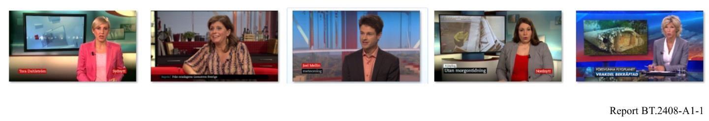
FIGURE A1-1
图 A1-1. 所分析图像的取样(由 SVT 与 FOX 提供)。
Due to the scarcity of HDR broadcast content currently available, in order to compare HDR and SDR content, the same analysis was completed utilizing HDR and SDR graded indoor scenes from cinematic content for home distribution. The cumulative histogram is given below.
由于目前可得的 HDR 广播内容稀少,为比较 HDR 与 SDR 内容,研究改用面向家庭发行的电影内容中、经 HDR 和 SDR 调色的室内场景,完成了同样的分析。累积直方图如下。
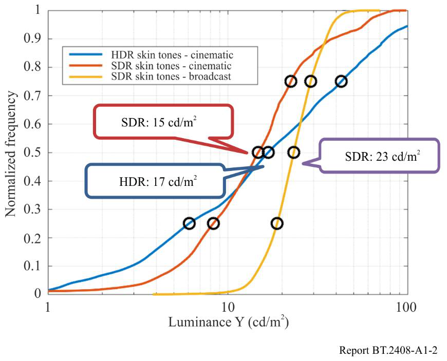
FIGURE A1-2 — Skin tone cumulative histogram
图 A1-2. 肤色累积直方图。
For cinematic content for the home, HDR Caucasian skin tones are very similar to SDR skin tones (17 cd/m2 compared to 15 cd/m2), but the standard deviation is larger. Extrapolating from this, it is hypothesized that indoor Caucasian skin tones in HDR broadcast may average 26 cd/m2 with a larger deviation than SDR broadcast. The 26 cd/m2 value maps to 38% of full scale in PQ space (or 38%PQ).
对面向家庭的电影内容而言,HDR 白种人肤色与 SDR 肤色十分相近(17 cd/m² 对 15 cd/m²),但标准差更大。由此外推,假设 HDR 广播中室内白种人肤色的平均值可能为 26 cd/m²,且离散度大于 SDR 广播。26 cd/m² 这一数值在 PQ 空间对应满量程的 38%(即 38% PQ)。
Utilizing skin tones as a reference level is, of course, not satisfactory because they vary widely across ethnicities and environments. To achieve consistency, an 18% grey card may be used instead to calibrate camera exposure. To convert from Caucasian skin tone brightness and its 38%PQ level to find the %PQ level of an 18% grey card, a database of 340 measured samples of skin tones (Sun, Fairchild) was used to determine skin tone reflectance levels. This database shows that Caucasian skin tones have a reflectivity of 25% of that of a diffuse white object (white card: 100% Lambertian reflector).
用肤色作为参考电平当然并不理想,因为肤色因种族和环境而差异很大。为求一致,可改用 18% 灰卡来校准相机曝光。为从白种人肤色亮度及其 38% PQ 电平推算出 18% 灰卡的 %PQ 电平,研究使用了一个含 340 个肤色实测样本的数据库(Sun、Fairchild)来确定肤色反射率电平。该数据库表明,白种人肤色的反射率为漫反射白物体(白卡:100% 朗伯反射体)的 25%。
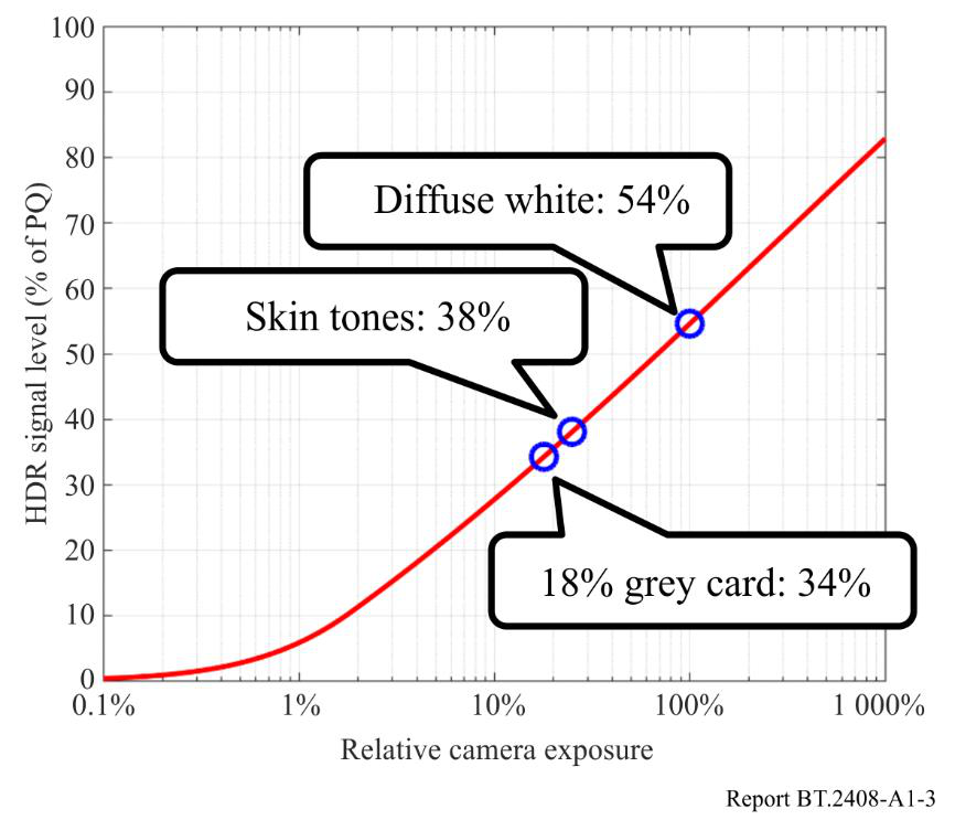
FIGURE A1-3 — BT.2100 reference OOTF
图 A1-3. BT.2100 参考 OOTF。
Using the BT.2100 reference PQ OOTF, 26 cd/m2 may be related to relative scene exposure. Then the 25% and 18% reflectivity relationship may be used to solve for the appropriate 18% grey card level: 17 cd/m2 on a PQ reference display or 34% on the PQ scale. This is the expected luminance for a grey card anchor in HDR broadcast content for indoor scenes, for content consistent with existing practice. A diffuse white would be expected to yield 54%PQ.
利用 BT.2100 参考 PQ OOTF,可把 26 cd/m² 与相对场景曝光联系起来;再用 25% 与 18% 反射率的关系,即可解出合适的 18% 灰卡电平:在 PQ 参考显示设备上为 17 cd/m²,即 PQ 刻度上的 34%。对与现有实践相符的内容而言,这就是 HDR 广播室内场景内容中灰卡锚点的预期亮度。漫反射白则预计对应 54% PQ。
By segmenting HDR indoor and outdoor scenes, it was found that outdoor skin tones were an average of 1.7 stops brighter than indoor skin tones. Assuming a 1.7 stop increase in brightness from an indoor to outdoor scene, the exposure for an 18% grey card outdoors would be set to 45%PQ.
通过分割 HDR 室内和室外场景,发现室外肤色平均比室内肤色亮 1.7 挡(stop)。假定从室内到室外场景亮度增加 1.7 挡,则室外 18% 灰卡的曝光应设为 45% PQ。
The Table below summarizes Dolby’s findings for current content; these values could be considered tentative recommendations on settings of an 18% grey card and diffuse white objects in terms of both %PQ value and reference display brightness.
下表汇总了杜比对当前内容的研究结果;这些数值可视为关于 18% 灰卡和漫反射白物体设置的初步推荐,以 %PQ 值和参考显示亮度两种方式给出。
| 项目 | 室内 cd/m² | 室内 %PQ | 室外 cd/m² | 室外 %PQ |
|---|---|---|---|---|
| 18% 灰卡 | 17 | 34 | 57 | 45 |
| 漫反射白 | 140 | 54 | 425 | 66 |
The levels shown in this study are representative of some early HDR PQ content. More experience with HDR in broadcast is needed to settle on final values to be recommended. A major finding is that early HDR production has employed skin levels similar to those used in SDR content. The SDR skin levels are of necessity limited in order to leave room for full diffuse whites, and some trace of highlights. HDR signals have enough range that skin levels do not need such limitations. Given that in HDR production there is no need to limit the skin levels to those used in SDR production, it is possible that these may increase in brightness in subsequent productions. Thus, the values in the Table above might be considered the lower end of future operating levels.
本研究所示的电平代表了一些早期 HDR PQ 内容。要确定最终的推荐值,还需要更多广播 HDR 经验。一个重要发现是:早期 HDR 制作所用的肤色电平与 SDR 内容相近。SDR 肤色电平不得不受到限制,以便为完整的漫反射白和一丝高光留出空间;而 HDR 信号范围足够大,肤色电平无需这样的限制。鉴于 HDR 制作无需把肤色电平限制在 SDR 制作所用的水平,这些电平在日后的制作中有可能变亮。因此,上表中的数值或可视为未来运行电平的下限。
附件 2 — 参考电平分析
Annex 2 — Analysis of reference levels
A2.1 Introduction
A2.1 引言
The reference levels of Tables 1 and 2 of this Report are intended to provide guidance for the production of HDR content. This Annex presents a Technicolor analysis of existing content relative to several reference levels. The content chosen included frames from an HLG-based live broadcast, as well as a set of test images that were converted to PQ. The purpose of this Annex is to document how the defined reference levels relate to currently produced content, and to assess the variability in luma/luminance levels seen in current content.
本报告表 1 和表 2 的参考电平意在为 HDR 内容制作提供指导。本附件给出 Technicolor 对照若干参考电平所作的现有内容分析。所选内容包括来自一场基于 HLG 的直播的若干帧,以及一组转换为 PQ 的测试图像。本附件的目的是记录所定义的参考电平与当前所制作内容之间的关系,并评估当前内容中亮度信号/亮度电平的变动程度。
A2.2 Analysis of reference levels
A2.2 参考电平分析
Several reference levels are analysed in the context of a database of 107 linear EXR images, graded for a 1 000 cd/m2 display device. This dataset is included in Report ITU-R BT.2245. In this dataset the arithmetic mean luminance is 65.47 cd/m2 (standard deviation 83.99 cd/m2). The geometric mean luminance is 9.17 cd/m2 (standard deviation 24.74 cd/m2).
研究在一个含 107 幅线性 EXR 图像(为 1 000 cd/m² 显示设备调色)的数据库基础上分析了若干参考电平。该数据集收录于报告 ITU-R BT.2245。在该数据集中,算术平均亮度为 65.47 cd/m²(标准差 83.99 cd/m²),几何平均亮度为 9.17 cd/m²(标准差 24.74 cd/m²)。
To understand how a given recommended reference level relates to the content presented in this database, the percentage of pixels that have values larger than the reference level is calculated. For each image, this percentage will be different, giving rise to a distribution of percentages. Then, a range of percentages was calculated that represents the 95% confidence interval. This means that this range of percentages represents 95% of the images in the database. To determine a confidence interval, the following equation was used:
为了解某个推荐参考电平与该数据库所含内容之间的关系,计算了取值高于该参考电平的像素所占百分比。对每幅图像,这一百分比各不相同,从而形成一个百分比分布。然后计算出代表 95% 置信区间的百分比范围,这意味着该百分比范围涵盖数据库中 95% 的图像。确定置信区间所用公式如下:
where:
n = 107 : number of images analysed
x: mean number of pixels above the selected reference level
σ: associated standard deviation.
式中:
- n = 107:所分析的图像数;
- x̄:高于所选参考电平的像素数均值;
- σ:相应的标准差。
The value of z∗ is 1.96 for a 95% confidence interval. Likewise, the 99% confidence interval is computed, using a value of z∗ of 2.58. The results are shown in Table A2-1.
95% 置信区间的 z* 值为 1.96。同样,99% 置信区间用 z* = 2.58 计算。结果见表 A2-1。
表 A2-1. 在 1 000 cd/m² 图像数据集上,给出取值高于各参考亮度电平的像素百分比的 95% 与 99% 置信区间
| 描述 | 亮度(范围) | 95% 置信区间 | 99% 置信区间 |
|---|---|---|---|
| 灰卡(18%) | 26 | 33.21%–45.87% | 32.21%–47.88% |
| 灰阶图卡最高级(83%) | 162 | 8.89%–16.23% | 7.73%–17.39% |
| 灰阶图卡最高级(90%) | 179 | 7.82%–14.77% | 6.72%–15.87% |
| HDR 参考白 | 203 | 6.65%–13.10% | 5.62%–14.13% |
| 草地 | 30–65 | 19.82%–43.41% | 18.16%–45.37% |
| 冰场 | 155 | 9.37%–16.90% | 8.18%–19.09% |
| 白色物体 | 140–425 | 1.79%–18.59% | 1.25%–19.85% |
Further, the same set of images were analysed to understand which luminance level marks the threshold so that 1% of the pixels lies above this level. This calculation was repeated for 5%, 10% and 20% of the pixels. The results are shown in Table A2-2.
此外,对同一组图像作了分析,以确定哪个亮度电平为阈值时恰有 1% 的像素高于该电平。对 5%、10%、20% 的像素重复了这一计算。结果见表 A2-2。
表 A2-2. 在一组 107 幅 HDR 图像中标示出最高 N% 像素的亮度电平
| 百分位 | 均值(标准差),cd/m² |
|---|---|
| 1% | 321.89(262.14) |
| 5% | 195.04(206.15) |
| 10% | 145.03(170.56) |
| 20% | —(145.01) |
译注:原文表中 20% 一行只给出括号内数值(145.01),均值数字在原始 PDF 中缺失,此处照原文保留。
A2.3 Diffuse white elements in live HLG encoded broadcast content
A2.3 HLG 编码直播广播内容中的漫反射白元素
Diffuse white elements6 in HLG encoded live broadcast content (“Dodgers Game”) were analysed by taking one frame every five seconds and manually clicking in each frame on patches that appeared to represent diffuse white elements which were directly illuminated, without being over-exposed. The total number of analysed frames was 152, and the number of diffuse white points identified in this manner is 378. The content was a baseball game, interspersed with commercials, and containing scenes from a game played in daylight and a game played at night under artificial illumination.
对 HLG 编码直播广播内容(“道奇队比赛”)中的漫反射白元素[6]进行了分析:每五秒取一帧,并在每帧中人工点击看似代表受直接照明、未过曝的漫反射白元素的色块。所分析的帧共 152 帧,以此方式识别出的漫反射白点共 378 个。内容为一场棒球比赛,其间穿插广告,包含白昼比赛和夜间人工照明下比赛的场景。
The pixels identified in the manner described above represent values as %HLG. Statistics (mean, standard deviation, minimum and maximum RGB values) are given in the %HLG column of Table A2-3. These numbers were subsequently converted to cd/m2 assuming a display peak luminance of 1 000 cd/m2 , and to %PQ. These values are also reported in Table A2-3. Finally, Fig. A2-1 shows a histogram of the distribution of diffuse white levels for each of the red, green and blue channels, with the horizontal axis indicating values in %HLG.
以上述方式识别出的像素,其值以 %HLG 表示。统计量(均值、标准差、最小及最大 RGB 值)列于表 A2-3 的 %HLG 列。这些数值随后在假定显示峰值亮度为 1 000 cd/m² 的前提下换算为 cd/m²,并换算为 %PQ,也列于表 A2-3。最后,图 A2-1 给出红、绿、蓝各通道漫反射白电平分布的直方图,横轴为 %HLG 值。
表 A2-3. HLG 编码直播广播内容的漫反射白分析。%HLG 列为实测值,其余各列由实测值推导(152 帧,378 点)
| 漫反射白 | cd/m² | %HLG | %PQ |
|---|---|---|---|
| 均值 | (222.1, 204.3, 231.3) | (76.6, 75.0, 77.4) | (59.0, 58.1, 59.4) |
| 标准差 | (134.7–373.5;123.6–345.4;141.0–386.7) | (8.3, 8.4, 8.2) | — |
| 最小 | (44.6, 44.5, 48.9) | (47.4, 47.3, 49.6) | (42.9, 42.9, 44.0) |
| 最大 | (747.1, 735.3, 789.9) | (95.6, 95.3, 96.6) | (72.0, 71.8, 72.6) |
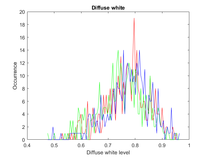
FIGURE A2-1 — Distribution of diffuse white patches in HLG live broadcast content. The values on the horizontal axis are in %HLG
图 A2-1. HLG 直播广播内容中漫反射白色块的分布。横轴数值以 %HLG 表示。
A2.4 Diffuse white in an HDR dataset of 1 000 cd/m2 PQ encoded images
A2.4 1 000 cd/m² PQ 编码图像 HDR 数据集中的漫反射白
A dataset of 54 EXR images containing diffuse white patches was analysed using the same methodology as described in § A2.3. The dataset contains images that are graded for a 1 000 cd/m2 display device. The linear EXR images were first PQ encoded. A total of 169 white patches were identified, producing the distribution shown in Fig. A2-2 and the derived statistics shown in Table A2-4. In this Table, the %PQ column was measured from the pixels that were selected, whereas the columns indicated with cd/m2 and %HLG were calculated from the %PQ column.
采用与 A2.3 节相同的方法,分析了一个含 54 幅、带漫反射白色块的 EXR 图像数据集。该数据集所含图像是为 1 000 cd/m² 显示设备调色的。先把线性 EXR 图像作 PQ 编码,共识别出 169 个白色块,得到图 A2-2 所示分布和表 A2-4 所示的推导统计量。在该表中,%PQ 列由所选像素实测得到,而标注 cd/m² 和 %HLG 的各列则由 %PQ 列计算得出。
表 A2-4. PQ 编码内容的漫反射白分析。%PQ 列为实测值,其余各列由实测值推导(54 帧,169 点)
| 漫反射白 | cd/m² | %HLG | %PQ |
|---|---|---|---|
| 均值 | (231.8, 244.2, 193.3) | (77.1, 78.1, 73.5) | (59.5, 60.0, 57.6) |
| 标准差 | (76.6–665.6;80.6–703.4;58.9–594.1) | — | (11.3, 11.3, 12.0) |
| 最小 | (5.6, 7.0, 6.7) | (19.7, 22.0, 21.5) | (25.6, 27.2, 27.0) |
| 最大 | (903.0, 1 000.0, 946.5) | (98.2, 100, 99.1) | (74.1, 75.2, 74.6) |
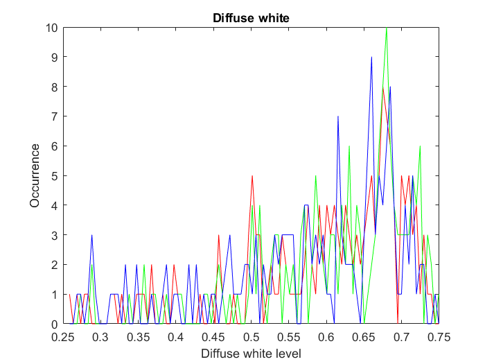
FIGURE A2-2 — Distribution of Diffuse White patches in a test database of 1 000 cd/m2 images. The values on the horizontal axis are in %PQ
图 A2-2. 1 000 cd/m² 图像测试数据库中漫反射白色块的分布。横轴数值以 %PQ 表示。
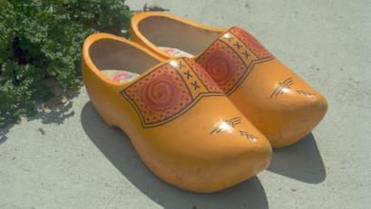
FIGURE A2-3 — An image with 1.4% of its pixels above diffuse white (prior to tone mapping for display)
图 A2-3. 一幅有 1.4% 像素高于漫反射白的图像(在为显示作色调映射之前)。
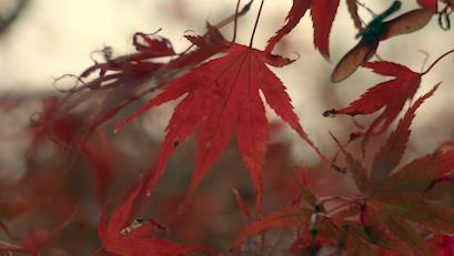
FIGURE A2-4 — An image with 17% of its pixels with values above diffuse white (prior to tone mapping for display)
图 A2-4. 一幅有 17% 像素取值高于漫反射白的图像(在为显示作色调映射之前)。
A2.5 Discussion
A2.5 讨论
Two types of analyses were performed to help understand the relationship with pre-defined reference levels and content. In the first analysis, the number of pixels that have values higher than a given reference level was computed. A 95% and a 99% confidence interval was calculated, indicating the percentage of pixels that may be expected to be above the reference level.
为帮助理解预定义参考电平与内容之间的关系,进行了两类分析。第一类分析计算取值高于某给定参考电平的像素数,并算出 95% 和 99% 置信区间,指出可预期高于该参考电平的像素百分比。
For HDR Reference White, for example, it was determined that 99% of the images have between 5.6% and 14% of their pixels result in levels greater than 203 cd/m2 in a set of 107 HDR images that were graded at 1 000 cd/m2 . Likewise, 95% of the same images have between 6.6% and 13% of their pixels larger than 203 cd/m2 .
以 HDR 参考白为例,在一组 107 幅、按 1 000 cd/m² 调色的 HDR 图像中,确定有 99% 的图像其 5.6% 至 14% 的像素电平大于 203 cd/m²;同样,这些图像中有 95% 的图像其 6.6% 至 13% 的像素大于 203 cd/m²。
To illustrate, compare the images shown in Figs A2-3 and A2-4, which have 1.4% and 17% of their pixels above HDR reference white, respectively. Figure A2-3 shows a clear case of an image where the extra headroom afforded by HDR technologies is spent on the highlights. Figure A2-4, on the other hand, has a significant part of the sky in the background at values above 203 cd/m2 .
举例来说,比较图 A2-3 和图 A2-4,二者分别有 1.4% 和 17% 的像素高于 HDR 参考白。图 A2-3 是一个清晰的例子:HDR 技术所提供的额外余量用在了高光上。图 A2-4 则相反,其背景中很大一部分天空的取值高于 203 cd/m²。
In a second analysis, diffuse white was measured by manually identifying pixels in a set of frames/images. Over-exposed pixels were avoided, while diffuse white surfaces not receiving direct illumination were also excluded. The signal levels of white pixels were analysed. For the HLG-based live broadcast content, the mean diffuse white level was 75%HLG, which is the same as the recommended reference level in Table 1 – even if the content was produced without specifically using a target 203 cd/m2 for reference level. However, the standard deviation was about 8.3% (measured in %HLG), which – for an assumed 1 000 cd/m2 signal – translates to a range between around 123 and 345 cd/m2 (i.e. mean ± one standard deviation). This suggests that the diffuse white level as measured in live broadcast content varies significantly.
第二类分析通过在一组帧/图像中人工识别像素来测量漫反射白。避开了过曝像素,也排除了未受直接照明的漫反射白表面,分析了白像素的信号电平。对基于 HLG 的直播广播内容,漫反射白的均值电平为 75% HLG——这与表 1 的推荐参考电平相同,尽管该内容在制作时并未专门以 203 cd/m² 为参考电平目标。然而其标准差约为 8.3%(以 %HLG 计),对假定的 1 000 cd/m² 信号而言,这相当于约 123 至 345 cd/m² 的范围(即均值 ± 一个标准差)。这表明,直播广播内容中所测得的漫反射白电平变动很大。
These results are broadly replicated with the test set of 107 HDR images which are PQ encoded. Here, the mean diffuse white level was determined to be around 60%PQ, which is close to 58%PQ as recommended in Table 1. The standard deviation was 11% (in %PQ), however, which translates to a range between around 80 and 700 cd/m2 for mean ±1 standard deviation. The variability of diffuse white in this dataset is therefore significant, and it is larger than measured in the HLG-produced live broadcast content.
这些结果在 107 幅 PQ 编码 HDR 图像的测试集上大体得到重现。这里,漫反射白的均值电平确定为约 60% PQ,接近表 1 推荐的 58% PQ。但其标准差为 11%(以 %PQ 计),相当于均值 ± 一个标准差约为 80 至 700 cd/m² 的范围。因此,该数据集中漫反射白的变动也很显著,且大于在 HLG 制作的直播广播内容中所测得的。
A2.6 Conclusions
A2.6 结论
The HDR Reference White level of 203 cd/m2 in Table 1 of this Report is consistent with the mean diffuse white as measured in the content analysed in this Annex. However, the standard deviation of diffuse white in two different sources of content are large, indicating a significant spread of diffuse white around the mean.
本报告表 1 中 203 cd/m² 的 HDR 参考白电平,与本附件所分析内容中测得的漫反射白均值相一致。然而,两种不同来源内容中漫反射白的标准差都很大,表明漫反射白围绕均值有显著的离散。
附件 3 — 肤色的两项研究:基于反射率数据库与基于真人
Annex 3 — Two studies of skin tones, using a reflectance database and using real subjects
This Annex reports two studies of skin tones, one that uses an existing database of skin reflectances and a model of an ideal camera, and one that uses real subjects and RAW camera recording. Luma values are proposed for different skin tones in HLG high dynamic range video.
本附件报告关于肤色的两项研究:一项使用现有的皮肤反射率数据库和一台理想相机的模型,另一项使用真人和 RAW 相机录制。本附件为 HLG 高动态范围视频中不同肤色提出了亮度信号(luma)值。
A3.1 Study 1: using a skin tone database and an ideal model of a camera
A3.1 研究 1:使用肤色数据库和理想相机模型
A skin tone reflectance database from the US government National Institute of Standards and Technology (NIST) [9] was used for this study. The database covers a wide range of skin tones, however when comparing the 685 nm reflectances with those given elsewhere [10], it can be seen that it does not cover the full range of expected global reflectances.
本研究使用了美国政府国家标准与技术研究院(NIST)的肤色反射率数据库 [9]。该数据库涵盖很宽的肤色范围,但把其 685 nm 处的反射率与别处所给数据 [10] 相比可以看出,它并未涵盖全球预期反射率的全部范围。
The NIST database contains measures of skin reflectance of the inner forearm at a number of wavelengths. These tend to be slightly higher than the face. This dataset is shown in Fig. A3-1.
NIST 数据库包含前臂内侧在若干波长上的皮肤反射率测量值,这些值往往略高于面部。该数据集见图 A3-1。
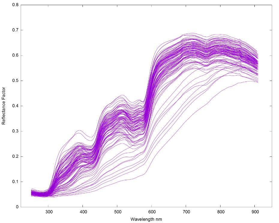
FIGURE A3-1 — NIST Dataset. Each line corresponds to one skin sample
图 A3-1. NIST 数据集。每条线对应一个皮肤样本。
A software model of an ideal camera and lighting scenario was used (illustrated in Fig. A3-2) to generate values for Hybrid Log-Gamma (HLG) luma.
研究使用了一个理想相机及照明情景的软件模型(见图 A3-2)来生成混合对数伽马(HLG)亮度信号值。
The model consists of a sample multiplied by the spectral curve of an ideal D65 illuminant [11] fed through an aperture (a fixed scalar). A set of CIE 1931 2 degree observer LMS to XYZ curves [12] are then used to convert to a known imaging format. These XYZ values are then converted to Recommendation ITU-R BT.2020/BT.2100 linear RGB values and the HLG Opto-Electronic Transfer Function (OETF) is applied. Finally, the luma value is calculated for the HLG R′G′B′ values.
该模型由样本乘以理想 D65 光源的光谱曲线 [11] 构成,再经过一个孔径(一个固定标量)。然后用一组 CIE 1931 2° 视场观察者的 LMS 到 XYZ 曲线 [12],转换到一种已知的成像格式。这些 XYZ 值再转换为建议书 ITU-R BT.2020/BT.2100 线性 RGB 值,并施加 HLG 光电转换函数(OETF)。最后,由 HLG R′G′B′ 值计算亮度信号值。
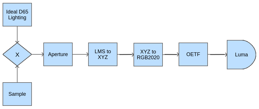
FIGURE A3-2 — Block diagram of ideal camera model
图 A3-2. 理想相机模型的框图。
The NIST data set, ideal D65 illuminant curves and LMS to XYZ curves all used different wavelength step sizes in presenting the data, so, where data points did not align, a linear interpolation was used.
NIST 数据集、理想 D65 光源曲线以及 LMS 到 XYZ 曲线在呈现数据时所用的波长步长各不相同,因此凡数据点不对齐处,均采用线性插值。
The first step in using the model was to calculate the required input aperture. By setting the input sample to a fixed value of 1.0 at all wavelengths to represent diffuse white, the aperture (a scalar) was adjusted such that the HLG luma value was equal to 0.75, the HLG signal level for HDR Reference White. This value of aperture was then used for all further samples.
使用该模型的第一步是计算所需的输入孔径。把输入样本在所有波长上设为固定值 1.0 以代表漫反射白,调整孔径(一个标量),使 HLG 亮度信号值等于 0.75,即 HDR 参考白的 HLG 信号电平。此后所有样本都使用这一孔径值。
The second step is to apply the model for each skin reflectance curve given in the NIST dataset. The results of this are shown in Fig. A3-3. Luma values are plotted against the skin reflectance at 685 nm to allow comparison with regional labelling from [10]. These regional labels have been added to the plot.
第二步是对 NIST 数据集中给出的每条皮肤反射率曲线施加该模型。结果见图 A3-3。亮度信号值相对 685 nm 处的皮肤反射率绘出,以便与文献 [10] 的地域标注作比较。这些地域标注已加到图上。
A further plot of skin tone reflectance against screen emittance for a 1 000 cd/m2 HLG display is given in Fig. A3-4.
图 A3-4 进一步给出针对 1 000 cd/m² HLG 显示设备的肤色反射率与屏幕辐出度的关系。
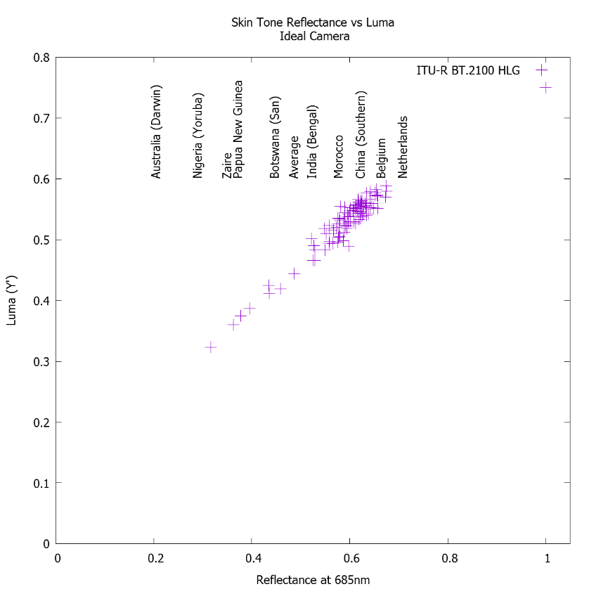
FIGURE A3-3 — Skin tone reflectance at 685 nm against HLG Luma for ideal camera, with regional labels from [10]
图 A3-3. 理想相机下 685 nm 处肤色反射率与 HLG 亮度信号的关系,附文献 [10] 的地域标注。
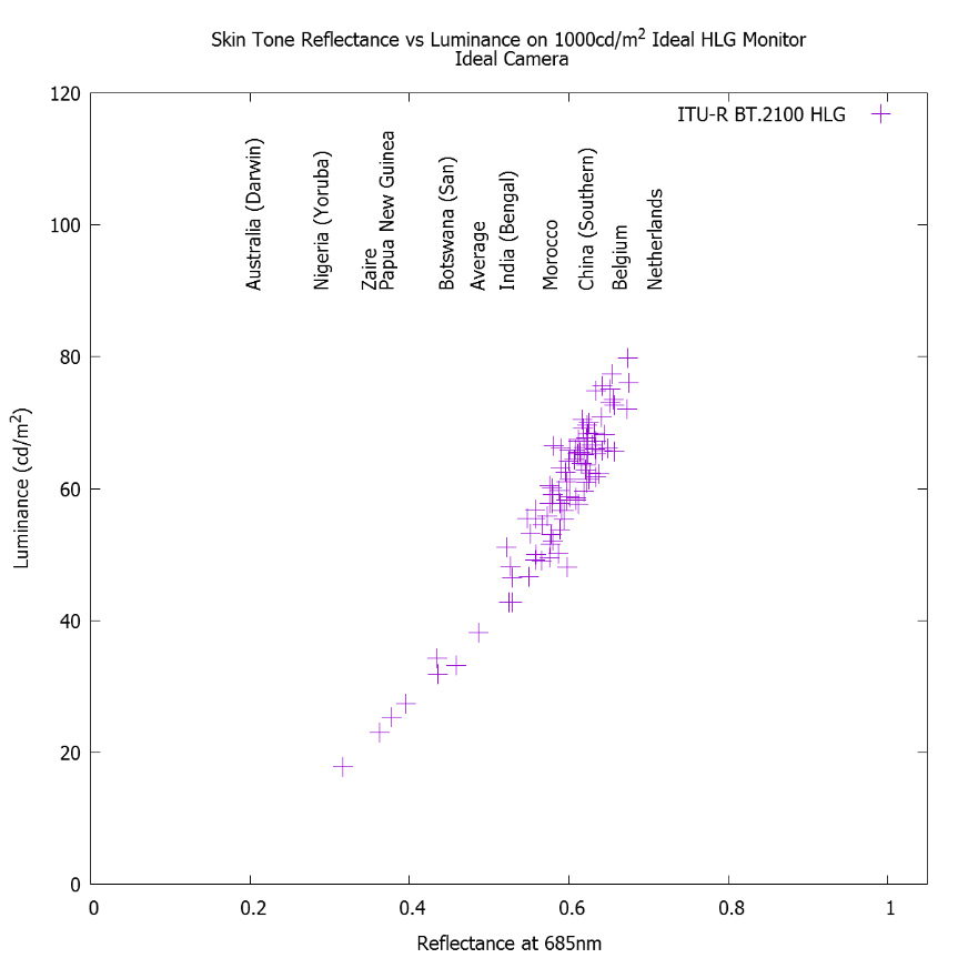
FIGURE A3-4 — Skin tone reflectance at 685 nm against HLG luminance on a 1 000 cd/m2 display, for ideal camera, with regional labels from [10]
图 A3-4. 理想相机下,1 000 cd/m² 显示设备上 685 nm 处肤色反射率与 HLG 亮度的关系,附文献 [10] 的地域标注。
A3.2 Study 2: using human subjects and a RAW recording camera
A3.2 研究 2:使用真人受试者和 RAW 录制相机
In conjunction with the European Broadcasting Union, a second experiment was conducted using real people and a DSLR RAW-recording camera. To categorise the subjects, the Fitzpatrick Skin Tone Scale [1] was used.
与欧洲广播联盟(EBU)合作,使用真人和一台 DSLR RAW 录制相机进行了第二项实验。为对受试者分类,采用了菲茨帕特里克肤色量表 [1]。
The first stage of the experiment was to calculate the reflectance of a small test chart that could be used in shot when photographing test subjects under practical D65 LED lighting. Using a Konika-Minolta CS2000 photospectrometer, the reflectances of the test chart white and black patches, a magnesium carbonate reference (97.5% reflectance) and a Gregory hole reference (black velvet lined box – 0% reflectance) were measured. The test chart white patch reflected 81.2% of light, the black patch 3.9%.
实验第一阶段是计算一张小测试图卡的反射率,以便在实际 D65 LED 照明下拍摄受试者时入镜使用。用 Konika-Minolta CS2000 分光光度计,测量了测试图卡白色块和黑色块、一个碳酸镁参考体(反射率 97.5%)以及一个格雷戈里孔参考体(黑色天鹅绒内衬盒——反射率 0%)的反射率。测试图卡白色块反射 81.2% 的光,黑色块反射 3.9%。
The processing chain for the images was designed to closely replicate the ideal camera workflow shown in Fig. A3-2. This is shown in Fig. A3-5. To convert the camera RAW file to linear XYZ, the open source package DCRaw [13] was used. This file was then processed to:
1 Convert the XYZ values to ITU-R BT.2020 linear RGB values and then to CIE Yu′v′;
2 Scale Y such that the average black patch pixel value equalled 3.9% and the average white patch pixel value equalled 81.2%, then convert back to ITU-R BT.2020 linear RGB values;
3 Apply the HLG OETF to the R, G and B channels (using the equations found in Recommendation ITU-R BT.2100) and then calculate the Y′ channel;
4 Crop two 50 pixel by 50 pixel areas of skin tone (forehead and cheek) and calculate the average luma value. Care was taken to ensure that the chosen areas are co-planar with the physical luminance ramp test chart.
图像的处理链经设计,尽量重现图 A3-2 所示的理想相机工作流,见图 A3-5。为把相机 RAW 文件转换为线性 XYZ,使用了开源软件包 DCRaw [13]。随后对该文件作如下处理:
- 把 XYZ 值转换为 ITU-R BT.2020 线性 RGB 值,再转换为 CIE Yu′v′;
- 缩放 Y,使黑色块像素均值等于 3.9%、白色块像素均值等于 81.2%,然后转换回 ITU-R BT.2020 线性 RGB 值;
- 对 R、G、B 通道施加 HLG OETF(使用建议书 ITU-R BT.2100 中的公式),然后计算 Y′ 通道;
- 裁取两块 50 像素 × 50 像素的肤色区域(额头和脸颊),计算亮度信号均值。注意确保所选区域与实体亮度渐变测试图卡共面。

FIGURE A3-5 — Real-life human skin tone measurement
图 A3-5. 真人肤色测量。
In order to match the test subject to the Fitzpatrick Scale classifications, a questionnaire from the Australian Government Radiation Protection and Nuclear Safety Agency was used [14].
为把受试者与菲茨帕特里克量表的分类相对应,使用了澳大利亚政府辐射防护与核安全局的一份问卷 [14]。
The results of these photographic tests are shown in Fig. A3-6. Skin tone measurements range from approximately 26%HLG to 67%HLG dependant on skin tone. It can also be seen that there is an issue with two peoples’ replies to the questionnaire. Both individuals are deeply pigmented and should either be type V or VI but have self-identified as type IV. Following discussions with these individuals, and others identifying as type IV, V or VI, it appears that there is an issue with the questions relating to tanning: people either reported that they were permanently tanned or that they never tanned, which led to changes in the result. Finally, it can be seen that there is a small difference across the face, with the forehead being more reflective than the cheek for persons with skin types II to IV.
这些拍摄测试的结果见图 A3-6。肤色测量值随肤色不同约在 26% HLG 到 67% HLG 之间。还可看出,有两人对问卷的回答存在问题:这两人肤色都很深,本应属第 V 或第 VI 型,却自报为第 IV 型。在与这两人以及其他自报为第 IV、V、VI 型者交谈后发现,问题出在与晒黑有关的提问上:人们要么报告自己常年晒黑,要么报告自己从不晒黑,从而导致结果偏差。最后还可看出,面部各处略有差异:第 II 至 IV 型肤色者的额头比脸颊反射率更高。
It should be noted that the event at which measurements were taken occurred in the Northern Hemisphere during winter (so few people were currently tanned) and the attendee demographic was skewed towards categories II, III and IV.
需要注意,进行测量的活动在北半球的冬季举行(因此当时晒黑者很少),且参加者的人群构成偏向第 II、III、IV 型。
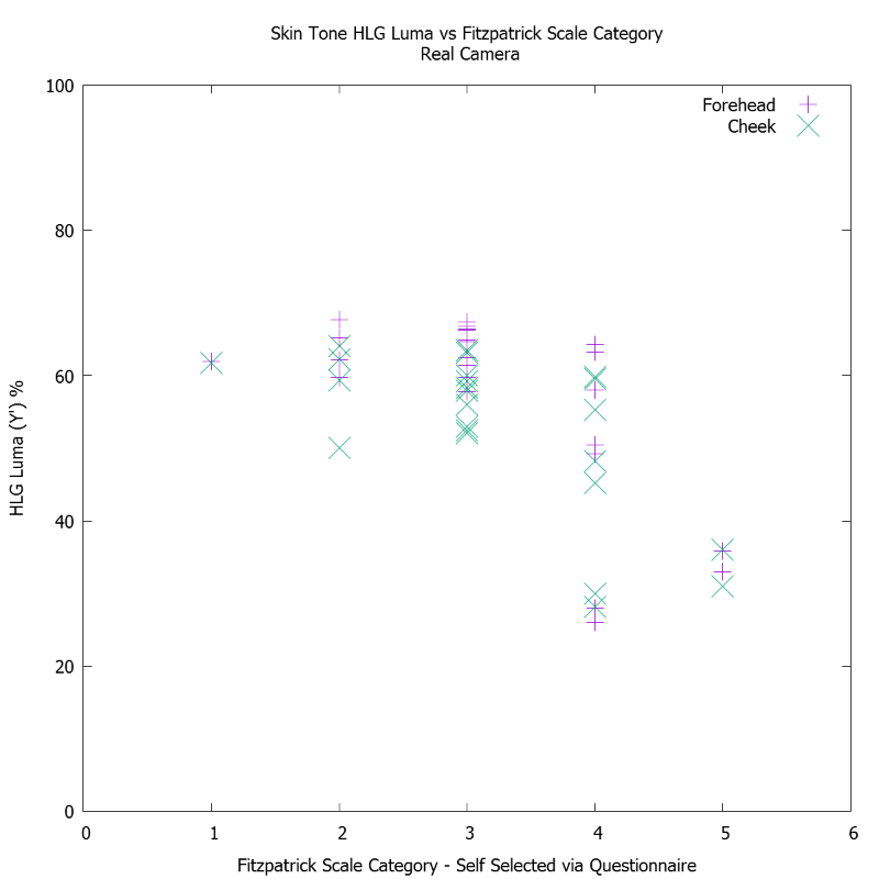
FIGURE A3-6 — HLG signal levels measured from human subjects
图 A3-6. 从真人受试者测得的 HLG 信号电平。
Based on these experimental results, Table A3-1 shows HLG luma ranges for each skin type. In formulating the values, the two people discussed previously in this section have been re-categorised as category VI, which gives values consistent with those presented in Fig. A3-3. To accurately represent the majority of the exposed skin which does not exhibit issues with perspiration shine, the ranges are chosen to cover the majority of the cheek skin tone measurements for each category, ignoring obvious outliers. A small amount of leeway is allowed at the bottom end of the ranges for categories I-IV to allow for summer tanning. Camera zebras should be set 2 to 3% above these ranges to take account of perspiration shine. Values are chosen to be easily used by productions using waveform monitors only.
基于这些实验结果,表 A3-1 给出各肤型的 HLG 亮度信号范围。在拟定这些数值时,把本节前面讨论的两人重新归为第 VI 型,从而得到与图 A3-3 一致的数值。为准确代表大多数不出现汗渍反光问题的裸露皮肤,各范围的选取覆盖了每个类别脸颊肤色测量值的大多数,并忽略明显的离群值。对第 I—IV 型,范围下端留有少量余地以计入夏季晒黑。相机斑马纹应设在这些范围之上 2 至 3%,以计入汗渍反光。所选数值便于仅使用波形监视器的制作使用。
表 A3-1. 不同肤型的 HLG 信号范围
| 菲茨帕特里克肤型 | HLG 信号电平(%HLG) |
|---|---|
| 第 I、II 型 | 55–65 |
| 第 III、IV 型 | 45–60 |
| 第 V、VI 型 | 25–45 |
A3.3 Conclusions
A3.3 结论
1 HLG luma levels measured with the DSLR camera (Study 2) are similar to those calculated with the computer camera model (Study 1).
2 Results are valid when the sample is from areas of skin co-planar with the physical test chart. Due to using a single light source, there is a marked drop off in reflectance when moving away from areas of the face that are co-planar. In one instance, the side of the face reflects less light than the black test colour on the chart.
3 There is an issue with ‘forehead shine’ caused by both perspiration under the studio lights and a matching of the angle of incidence and reflection such that light is reflected directly towards the camera.
4 The Australian Government questionnaire is designed to suggest levels of skin protection required in the southern hemisphere tropics and, therefore, is most suited to Fitzpatrick Skin Types I-IV. There is a possible mis-categorisation of two test subjects.
- 用 DSLR 相机测得的 HLG 亮度信号电平(研究 2)与用计算机相机模型计算所得(研究 1)相近。
- 当样本取自与实体测试图卡共面的皮肤区域时,结果有效。由于只用单一光源,离开面部共面区域后反射率明显下降。在一例中,脸的侧面反射的光甚至少于图卡上的黑色测试色。
- 存在“额头反光”问题,它由演播室灯光下的汗渍、以及入射角与反射角恰好使光直接朝相机反射这两者共同造成。
- 澳大利亚政府的问卷是为给出南半球热带地区所需的皮肤防护等级而设计的,因此最适合菲茨帕特里克第 I—IV 型肤色。其中可能有两名受试者被误分类。
附件 4 — 广播内容中面部肤色的研究
Annex 4 — Study of facial skin tones in broadcast content
This Annex reports on studies of facial skin tones in broadcast content in Japan.
本附件报告在日本对广播内容中面部肤色所作的研究。
A4.1 Facial skin tones in SDR news and information programmes in studio
A4.1 演播室 SDR 新闻与资讯节目中的面部肤色
Eight Japanese broadcasters contributed SDR broadcast content produced under controlled lighting in studios to this study. Table A4-1 shows the overview of the content. Target areas within a face, i.e. forehead and cheeks, were clipped out from the images and their average signal levels were measured.
八家日本广播机构为本研究提供了在演播室受控照明下制作的 SDR 广播内容。表 A4-1 给出这些内容的概览。从图像中裁取面部目标区域(即额头和脸颊),并测量其平均信号电平。
表 A4-1. 用于研究的演播室制作 SDR 广播内容
| 项目 | 内容 |
|---|---|
| 内容提供方 | 8 家日本广播机构⁽¹⁾ |
| 节目类型 | 演播室制作的新闻、资讯及谈话节目 |
| 取景类型 | 单人镜头、双人镜头和多人镜头 |
| 画面中人物 | 日本/蒙古人种男女 |
| 分析目标区域 | 额头和脸颊⁽²⁾ |
| 样本图像数 | 共 387 幅 |
| 分析面孔数 | 男:365,女:348,合计:713 |
(1) Japan Broadcasting Corp., Asahi Broadcasting Corp, Nippon Television Network Corp., Tokyo Broadcasting System Television, Fuji Television Network, TV Asahi Corp., TV Tokyo Corp., and WOWOW.
(2) Areas that exhibit the highest signal level within a face except for specular reflection and shine. A single person was charged with analysing the skin tones for consistent analysis.
注⑴:日本放送协会、朝日放送、日本电视网、东京广播系统电视、富士电视网、TV 朝日、TV 东京以及 WOWOW。
注⑵:指面部中除镜面反射和反光外信号电平最高的区域。为保持分析一致,由一人专门负责肤色分析。
Figure A4-1 shows the cumulative histogram of the facial skin tones. The average video levels (Y′) and standard deviations for male, female, and total are 71.8 (=5.2), 77.6 (=5.7), and 74.6 (=6.2) %SDR, respectively. These video levels correspond to luminance of 45 cd/m2, 55 cd/m2, and 49 cd/m2 on a display with the peak luminance of 100 cd/m2. The luminance of facial skin tones is more than twice the 23 cd/m2 reported in Annex 1 for SDR broadcast content.
图 A4-1 给出面部肤色的累积直方图。男性、女性、合计的平均视频电平(Y′)及标准差分别为 71.8(σ=5.2)、77.6(σ=5.7)、74.6(σ=6.2)%SDR。这些视频电平在峰值亮度 100 cd/m² 的显示设备上分别对应 45 cd/m²、55 cd/m²、49 cd/m² 的亮度。面部肤色的亮度是附件 1 中所报告 SDR 广播内容 23 cd/m² 的两倍多。
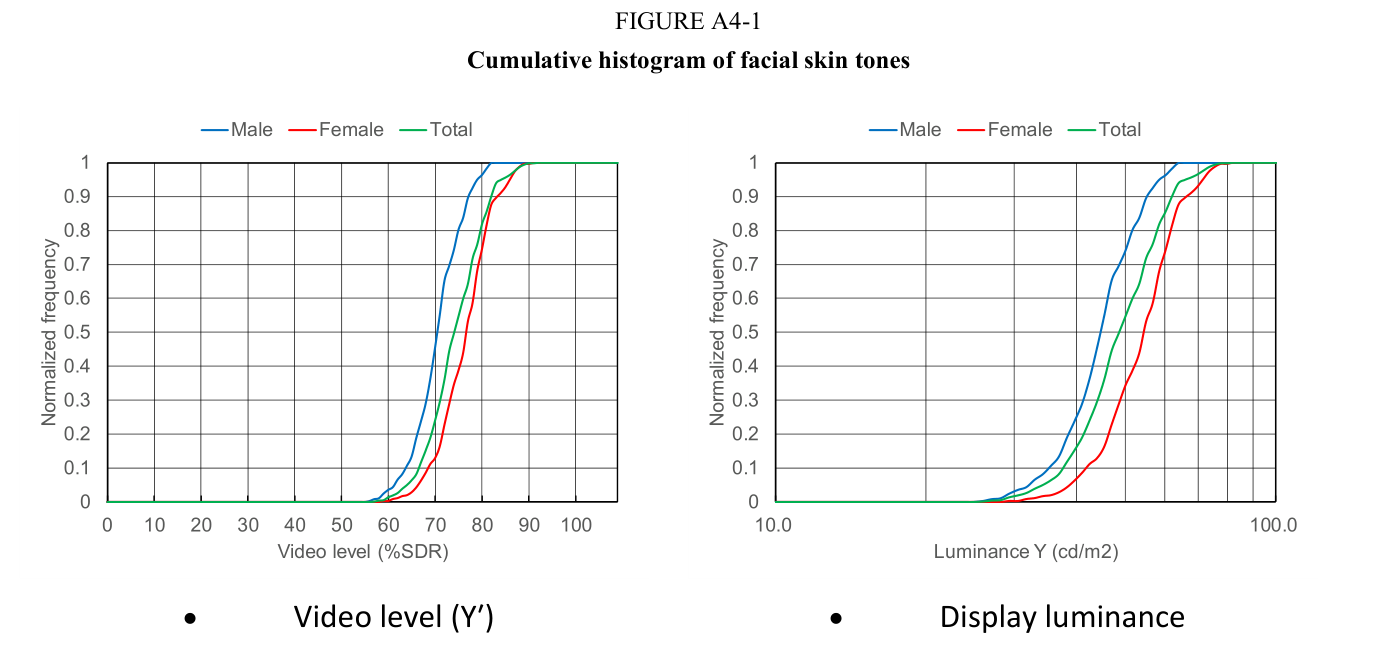
FIGURE A4-1 — Cumulative histogram of facial skin tones
图 A4-1. 面部肤色的累积直方图。(左:横轴为视频电平 %SDR;右:横轴为亮度 Y,cd/m²。图例:男、女、合计;点为视频电平 Y′/显示亮度。)
Facial skin reflectance was estimated in one of the SDR programmes, in which video level of facial skin was 81%SDR (Y′), by placing the 11-step grey scale chart at the caster’s position under the same lighting and exposure conditions in the studio. From the measurement, the reflectance of the facial skin was estimated to be 31% for luminance.
在其中一档面部皮肤视频电平为 81% SDR(Y′)的 SDR 节目中,通过在演播室相同照明和曝光条件下、把 11 级灰阶图卡放在主播位置,估算了面部皮肤反射率。由测量结果估算,面部皮肤的亮度反射率为 31%。
A4.2 Comparison of facial skin tones in HLG HDR and SDR content in a music programme
A4.2 一档音乐节目中 HLG HDR 与 SDR 内容面部肤色的比较
A preliminary study was conducted on skin tones in HLG HDR content in comparison with SDR content. Both HLG and SDR content were produced independently for the same NHK music programme in a concert where musicians performed on stage under special lighting and set. In the HDR production, video engineers paid attention to the reference level of 75%HLG. 75%HLG was also used for graphics white in captions.
对 HLG HDR 内容与 SDR 内容中的肤色作了初步比较研究。HLG 与 SDR 两种内容是为同一档 NHK 音乐节目各自独立制作的——这是一场音乐会,乐手在特殊灯光和布景下登台演出。在 HDR 制作中,视频工程师注意遵守 75% HLG 的参考电平;字幕中的图形白也采用 75% HLG。
The facial skin tones of 11 people (musicians and hosts) from 24 scenes in each of the HLG and SDR programmes were analysed. Figure A4-2 plots average levels of each face. The facial skin tones were found to be 45-56%HLG (50%HLG on average) and 41-71 cd/m2 on HLG displays with a peak luminance of 1 000 cd/m2, and 61-82%SDR (70%SDR on average) and 32-63 cd/m2 on SDR displays with a peak luminance of 100 cd/m2.
分析了 HLG 与 SDR 两档节目各 24 个场景中 11 人(乐手和主持人)的面部肤色。图 A4-2 绘出每张面孔的平均电平。结果发现,面部肤色在峰值亮度 1 000 cd/m² 的 HLG 显示设备上为 45—56% HLG(平均 50% HLG)、41—71 cd/m²;在峰值亮度 100 cd/m² 的 SDR 显示设备上为 61—82% SDR(平均 70% SDR)、32—63 cd/m²。
The values for SDR correspond well to those for the SDR news and information programmes in studio described in § A4.1. Since the HLG signal level for 30% reflectance is 49%HLG when 75%HLG corresponds to 100% reflectance, the skin tones in the HLG programme well match the HDR reference level.
SDR 的数值与 A4.1 节所述演播室 SDR 新闻资讯节目的数值吻合良好。由于当 75% HLG 对应 100% 反射率时,30% 反射率对应的 HLG 信号电平为 49% HLG,因此该 HLG 节目中的肤色与 HDR 参考电平很好地吻合。
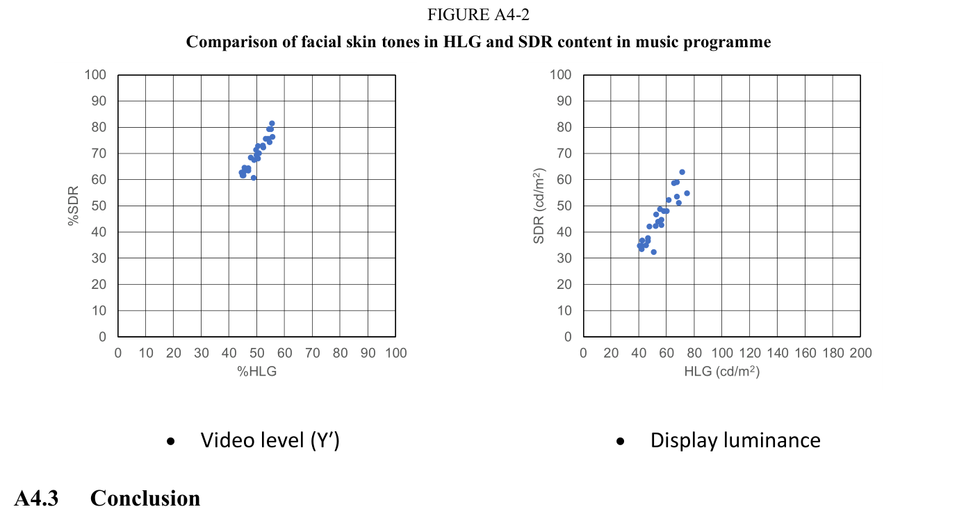
FIGURE A4-2 — Comparison of facial skin tones in HLG and SDR content in music programme
图 A4-2. 音乐节目中 HLG 与 SDR 内容面部肤色的比较。(左:纵轴 %SDR,横轴 %HLG;右:纵轴 SDR cd/m²,横轴 HLG cd/m²。点为视频电平 Y′/显示亮度。)
A4.3 Conclusion
A4.3 结论
Facial skin tones in SDR content in news and information programmes in studios and those in HDR and SDR content in a music programme in a concert hall were studied. The results are summarized in Table A4-2. The facial skin tones in Japanese SDR programmes were found to be much higher than those reported for European and American programmes in Annex 1. This may be mainly due to a difference in long-standing production practice for SDR rather than a difference in skin reflectance. It should also be noted that makeup also affects skin tones significantly.
研究考察了演播室新闻资讯节目 SDR 内容中的面部肤色,以及音乐厅一档音乐节目 HDR 与 SDR 内容中的面部肤色。结果汇总于表 A4-2。日本 SDR 节目中的面部肤色远高于附件 1 所报告的欧美节目。这可能主要源于长期以来 SDR 制作实践的差异,而非皮肤反射率的差异。还需注意,化妆也会显著影响肤色。
The relationship in facial skin tones between HDR and SDR should provide a foundation for establishing guidelines for converting HDR content into SDR and vice versa. Although HDR production is anticipated to universally follow the HDR reference levels described in this Report, different conversion characteristics may be needed for the conversion from HDR to SDR to obtain SDR pictures with familiar facial look in different regions or countries, yet more research is desirable.
HDR 与 SDR 之间面部肤色的关系,应为制定 HDR 内容与 SDR 内容相互转换的指南奠定基础。尽管预计 HDR 制作将普遍遵循本报告所述的 HDR 参考电平,但要在不同地区或国家获得面部观感为人所熟悉的 SDR 画面,HDR 到 SDR 的转换可能需要不同的转换特性,仍有待更多研究。
表 A4-2. 日本内容中面部肤色汇总
| 项目 | 演播室新闻与资讯(SDR) | 音乐厅音乐节目(SDR) | 音乐厅音乐节目(HLG) |
|---|---|---|---|
| 格式 | SDR | SDR | HLG |
| 图形白 | 100%SDR | 100%SDR | 75%HLG |
| 平均肤色 · 信号电平 | 男 72%SDR/女 78%SDR/合计 75%SDR | 70%SDR | 50%HLG |
| 平均肤色 · 显示亮度 | 男 45/女 55/合计 49 cd/m²(100 cd/m² 峰值显示) | 45 cd/m²(100 cd/m² 峰值显示) | 55 cd/m²(1 000 cd/m² 峰值显示) |
附件 5 — PQ 的显示——EETF 的计算
Annex 5 — Displaying PQ – calculating the EETF
This Annex describes approaches to mapping HDR signals to displays with a lower dynamic range, i.e. how to calculate the necessary EETF (electrical-electrical transfer function) in order to adapt to the display, see § 3.1.1. Such mapping may also be required during conversion from PQ to HLG.
本附件描述把 HDR 信号映射到动态范围较低显示设备上的方法,即如何计算为适配显示设备所需的 EETF(电-电转换函数),见 3.1.1 节。由 PQ 转换为 HLG 时也可能需要这种映射。
The central region of the tone mapping curve is defined as a 1:1 mapping. A ‘knee’ roll off may be calculated using a hermite spline to create a mapping that will reduce the luminance range to the capability of the display. The black level lift is controlled by an offset, b, which may be determined by a PLUGE adjustment as specified in Recommendation ITU-R BT.814. The difference between this proposal and the black level adjustment per Recommendation ITU-R BT.1886 is the addition of a tapering factor (1 – E2)4. Without such a tapering factor, a constant offset throughout the entire signal range has the effect of increasing the brightness at the high end. With Recommendation ITU-R BT.1886 this effect was limited and not problematic due to the large number of code values at the high end of the gamma curve. The perceptual uniformity of the PQ EOTF causes this effect to be unacceptable. The tapering function allows fine-tuning the lift without a significant impact on mid-tones or highlights.
色调映射曲线的中段定义为 1∶1 映射。可用埃尔米特样条(hermite spline)计算一段“拐点”滚降,构造出把亮度范围压缩到显示设备能力之内的映射。黑位抬升由偏置量 b 控制,可按建议书 ITU-R BT.814 规定,用 PLUGE 调整来确定。本方案与建议书 ITU-R BT.1886 的黑位调整之区别,在于增加了一个渐减因子 (1 − E2)⁴。若没有这个渐减因子,贯穿整个信号范围的恒定偏置会在高端起到增亮的作用。在建议书 ITU-R BT.1886 中,由于伽马曲线高端码值众多,这一效应有限、并不成问题;而 PQ EOTF 的感知均匀性,使这一效应变得不可接受。渐减函数可在不显著影响中间调或高光的情况下微调抬升量。
In the case where the mastering display minimum black and peak white luminances are known or reasonably can be assumed, the first step in applying the EETF is to normalize the PQ values based on the mastering display black and white luminances, LB and LW:
当母版显示设备的最低黑亮度和峰值白亮度已知、或可合理假定时,施加 EETF 的第一步是依据母版显示设备的黑、白亮度 L_B 和 L_W,对 PQ 值作归一化:
where E′ is the I, Y′ or R′, G′, or B′ PQ component and E1 is the corresponding mastering display black and white normalized PQ component.
式中 E′ 为 I、Y′ 或 R′、G′、B′ 这些 PQ 分量之一,E1 为相应的、经母版显示黑白归一化的 PQ 分量。
In the case where the mastering display minimum black and peak white luminances are not known and reasonably cannot be assumed, a value of 0 can be used for LB and a value of 10 000 can be used for LW, corresponding to the entire PQ encoding luminance range.
当母版显示设备的最低黑亮度和峰值白亮度未知、也无法合理假定时,可取 L_B = 0、L_W = 10 000,对应 PQ 编码的整个亮度范围。
The next step is to calculate the mastering display black and white normalized PQ values, minLum and maxLum, corresponding to the target display minimum (Lmin) and maximum (Lmax) luminances, including ambient, as follows:
下一步是计算与目标显示设备最低(L_min)和最高(L_max)亮度(含环境光)相对应的、经母版显示黑白归一化的 PQ 值 minLum 和 maxLum,如下:
The next step is to calculate the 1:1 mapping and knee (E2). The turning point (KneeStart or KS) for the spline is the point where the roll off will begin, as follows:
下一步是计算 1∶1 映射和拐点(E2)。样条的转折点(KneeStart,简记 KS)即滚降开始之处,如下:
The next step is to solve for the EETF (E3) with given end points.
下一步是在给定端点下求解 EETF(E3):
Hermite spline equations:
埃尔米特样条方程:
The final step is to invert the normalization of the PQ values based on the mastering display black and white luminances, LB and LW, to obtain the target display PQ values.
最后一步是依据母版显示黑白亮度 L_B 和 L_W,对 PQ 值的归一化作逆运算,得到目标显示设备的 PQ 值:
The EETF may be applied in many colour representations [15]. Here are some options:
EETF 可在多种色彩表示中施加 [15]。以下是若干选项:
- ICTCP
1)ICTCP:
- Y′C′BC′R
2)Y′C′BC′R:
$$
(C’{B2}, C’{R2}) = \min\!\left(\frac{Y’_1}{Y’_2}, \frac{Y’2}{Y’1}\right) \times (C’{B1}, C’{R1})
$$
- YRGB
3)YRGB:
- R′G′B′
4)R′G′B′:
- maxRGB
5)maxRGB:
As summarized in Table A5-1, since the ICTCP Y′C′BC′R, and YRGB methods can produce colours significantly outside the destination gamut, the degree to which these methods preserve the creative intent can be dependent on the gamut mapping used.
如表 A5-1 所汇总,由于 ICTCP、Y′C′BC′R 和 YRGB 三种方法都可能产生明显落在目标色域之外的色彩,这些方法保留创作意图的程度可能取决于所用的色域映射。
表 A5-1. EETF 各施加空间的优势
| ICTCP | Y′C′BC′R | YRGB | R′G′B′ | maxRGB | |
|---|---|---|---|---|---|
| 不会产生明显落在目标色彩体积之外的色彩 | ✕ | ✕ | ✕ | ✓ | ✓ |
It is possible to blend results from multiple methods. For example, with highlight compression, desaturation and hue changes can be controlled to some extent without requiring gamut mapping by using a blend of R′G′B′ with maxRGB.
可以把多种方法的结果加以混合。例如在压缩高光时,用 R′G′B′ 与 maxRGB 的混合,可在不需要色域映射的情况下,一定程度上控制去饱和与色相变化。
The degree to which the creative intent is maintained also depends on the amount of tone and colour compression applied, with more compression producing more significant differences. See Report ITU-R BT.2446 for methods for converting between HDR and SDR.
创作意图保持的程度还取决于所施加的色调和色彩压缩量,压缩越多,差异越显著。HDR 与 SDR 之间的转换方法见报告 ITU-R BT.2446。
The following is a short list expanding on the characteristics of each mapping space:
下面简要展开说明各映射空间的特性:
ICTCP
1 Has the potential to produce colours outside the destination gamut, which then require gamut mapping.
2 Since it is a perceptual colour difference space, it is a good space for gamut mapping. No need to convert to a different colour space if gamut boundary information and appropriately configurable gamut mapping algorithms are available.
3 Includes a desaturation function to produce a ‘natural’ looking desaturation where the source image lightness is changed by the EETF. Natural refers to the desaturation that results from the roll-offs in the human visual system response with colours that are extremely darker or extremely lighter than the adapted luminance. A common example is walking out of a dark theatre into the sun – initially the outdoor colours will look very bright and ‘washed out’.
4 Preserves hue in ICTCP space, which should be close to preserving perceptual hue due to the design of the ICTCP space.
ICTCP
- 有可能产生落在目标色域之外的色彩,因而需要色域映射。
- 由于它是感知色差空间,是适合作色域映射的空间。若已有色域边界信息和可适当配置的色域映射算法,则无须转换到其他色彩空间。
- 含有去饱和函数,当源图像明度被 EETF 改变时产生“自然”的去饱和。这里的“自然”,指当色彩远暗于或远亮于所适应亮度时,由人眼视觉系统响应的滚降所造成的去饱和。常见例子是从昏暗的影院走到阳光下——起初室外色彩会显得很亮、发白。
- 在 ICTCP 空间中保持色相;由于 ICTCP 空间的设计,这应当接近于保持感知色相。
Y′C′BC′R
1 Has the potential to produce colours outside the destination gamut, which then require gamut mapping.
2 The colour space can be used for gamut mapping. No need to convert to a different colour space if gamut boundary information and appropriately configurable gamut mapping algorithms are available.
3 Includes a desaturation function to produce a ‘natural’ looking desaturation where the source image lightness is changed by the EETF.
4 Preserves hue in the nonlinear Y′C′BC′R space, which departs in some areas from perceptual hue but can still produce acceptable results.
Y′C′BC′R
- 有可能产生落在目标色域之外的色彩,因而需要色域映射。
- 该色彩空间可用于色域映射。若已有色域边界信息和可适当配置的色域映射算法,则无须转换到其他色彩空间。
- 含有去饱和函数,当源图像明度被 EETF 改变时产生“自然”的去饱和。
- 在非线性 Y′C′BC′R 空间中保持色相;它在某些区域偏离感知色相,但仍能产生可接受的结果。
YRGB
1 Has the potential to produce colours outside the destination gamut, which then require gamut mapping.
2 Preserves chromaticity except for where gamut mapping is applied. Does not produce a ‘natural’ looking desaturation of tonally compressed colours.
3 Problems can be avoided by using in combination with a variable desaturation and gamut mapping algorithm, although such algorithms generally perform best in hue, saturation and lightness colour spaces (requiring a colour space change).
YRGB
- 有可能产生落在目标色域之外的色彩,因而需要色域映射。
- 除施加色域映射处外,能保持色品。但不会对经色调压缩的色彩产生“自然”的去饱和。
- 可通过与可变去饱和及色域映射算法结合使用来避免问题,尽管这类算法通常在色相、饱和度、明度色彩空间中表现最佳(需要更换色彩空间)。
R′G′B′
1 Does not produce colours outside the destination gamut.
2 Generally tends to produce ‘natural’ looking colours, although saturation of extreme colours is reduced substantially and some colours may be changed in hue.
3 Problematic when it is desired to retain bright saturated colours, such as coloured lights at night.
4 Depending on the amount of compression, the saturation decrease may be excessive, and occasionally hue changes can be objectionable.
5 Results depend on RGB primaries used. It has been found that primaries close to the BT.2020 primaries tend to work well.
R′G′B′
- 不会产生落在目标色域之外的色彩。
- 总体上倾向于产生“自然”的色彩,尽管极端色彩的饱和度会大幅降低,某些色彩的色相可能改变。
- 当希望保留明亮饱和的色彩(如夜间的彩色灯光)时,会有问题。
- 视压缩量而定,饱和度下降可能过度,色相变化偶尔会令人不快。
- 结果取决于所用的 RGB 基色。已发现接近 BT.2020 基色的基色往往效果良好。
maxRGB
1 Does not produce colours outside the destination gamut when used to compress highlights.
2 Preserves chromaticity at the expense of lightness.
3 Can produce un-natural colours that look like artifacts, due to lightness differences being compressed without associated saturation changes. Typical examples include very bright skin tones and sunsets where luminance differences are obscured. In these cases, other methods will produce better looking results.
4 Does a good job maintaining bright coloured lights.
maxRGB
- 用于压缩高光时,不会产生落在目标色域之外的色彩。
- 以牺牲明度为代价保持色品。
- 可能产生看似伪影的不自然色彩,因为明度差异被压缩、却没有相应的饱和度变化。典型例子包括非常明亮的肤色和落日,其中亮度差异被掩盖。这些情况下,其他方法会产生更好看的结果。
- 在保持明亮彩色灯光方面表现良好。
附件 6 — HDR 与 SDR 制作原生观感的比较
Annex 6 — Comparison of the native looks of HDR and SDR production
As mentioned in § 7.6.3, when colour matching cameras in live production, it is important to note that the native displayed ‘look’ of each SDR and HDR production format is different as, by design, they all have different OOTFs. Even though cameras usually provide ‘painting controls’ that adjust the OOTFs to deliver the desired artistic ‘look’, they are often insufficient to exactly match the displayed ‘look’ of cameras using the different formats. For that reason, when converting signals from different format cameras into a common format for live production, scene-light rather than display-light conversions are preferred, as they are agnostic to the OOTF differences.
如 7.6.3 节所述,在直播制作中对相机作色彩匹配时,要注意一点:各 SDR 与 HDR 制作格式原生显示的“观感”各不相同,因为它们按设计都有不同的 OOTF。尽管相机通常提供“调校控制”来调整 OOTF 以呈现所需的艺术“观感”,但这些控制往往不足以精确匹配使用不同格式的相机所显示的“观感”。正因如此,在把不同格式相机的信号转换为直播制作的共同格式时,更倾向于场景光转换而非显示光转换,因为前者对 OOTF 差异不敏感。
To quantify the differences in the displayed look of the different formats, the different television production formats BT.709, BT.2020, PQ, HLG, and HLG with traditional colour reproduction (as described in § 6.5 of Report ITU-R BT.2390) are compared based on their different renderings (different displayed light) of the same scene data, i.e. their different ‘native looks’, as determined by their different OOTFs. For each format, the display light is obtained by passing selected reference colour pattern data (a ‘colour chart’) through its OOTF, where the OOTF of each format is determined by the concatenation of its respective OETF (camera side) and EOTF (display side). The reference colour data is the television colour reference pattern of [16], which describes a colour chart containing three lines of six coloured swatches as well as one line of six neutral swatches (with different reflectances). To enable an objective comparison between the different formats, the luminance of the displayed white swatch (the neutral swatch with the highest reflectance) is normalized to approximately 200 cd/m2 for each format. This normalization is performed by linearly scaling the scene linear reference colour data (equivalent to adjusting the camera iris).
为量化不同格式所显示观感的差异,把 BT.709、BT.2020、PQ、HLG、以及采用传统色彩还原的 HLG(如报告 ITU-R BT.2390 第 6.5 节所述)这几种电视制作格式,依据它们对同一场景数据的不同呈现(不同的显示光)——即由各自不同 OOTF 所决定的不同“原生观感”——加以比较。对每种格式,显示光由所选的参考色彩图案数据(一张“色卡”)通过其 OOTF 得到,而各格式的 OOTF 由其各自的 OETF(相机端)与 EOTF(显示端)串接而定。参考色彩数据采用文献 [16] 的电视色彩参考图案,它描述了一张含三行各六个彩色色块、以及一行六个(反射率不同的)中性色块的色卡。为使不同格式之间可作客观比较,把所显示白色块(反射率最高的中性色块)的亮度对每种格式都归一化到约 200 cd/m²。这一归一化通过线性缩放场景线性参考色彩数据来实现(相当于调整相机光圈)。
The differences between the display light colour charts for the different formats can be characterized by the differences in chromaticity as well as luminance between the displayed colour swatches.
不同格式显示光色卡之间的差异,可由所显示色块之间色品和亮度的差异来刻画。
The CIE 1976 uniform chromaticity scale plot [17] of the display light chromaticity values for each format shows that the chromaticity differences between the different formats can be substantially characterized as saturation differences (the differences in hue between the formats are small). The HLG format, by design, has the lowest saturation of all formats because it preserves the chromaticity of the scene as imaged by the camera; all other formats increase saturation compared to the scene as imaged by the camera. Earlier studies have shown that colorimetrically accurate reproduction of natural scenes does not necessarily ensure the highest perceived image quality and a reliable enhancement of perceived image quality can be produced by selectively increasing saturation values [18]. Most cameras offer a saturation adjustment in the CCU to deliver artistically pleasing images.
把各格式显示光色品值绘成 CIE 1976 均匀色品标度图 [17],可见不同格式之间的色品差异基本上可刻画为饱和度差异(各格式之间的色相差异很小)。HLG 格式按设计在所有格式中饱和度最低,因为它保留了相机所成场景的色品;所有其他格式与相机所成场景相比都提高了饱和度。早先的研究表明,对自然场景作色度学上准确的还原未必能保证最高的感知图像质量,而有选择地提高饱和度值可可靠地提升感知图像质量 [18]。大多数相机在 CCU 中提供饱和度调整,以呈现艺术上悦目的图像。
When ranking the formats from low to high saturation for the non-neutral colour swatches in the chart, the ranking is as follows for average and median colour swatch saturation:
Average: HLG < HLG traditional colour < PQ < BT.709 < BT.2020
Median: HLG < BT.709 < HLG traditional colour < PQ < BT.2020
按色卡中非中性色块饱和度从低到高对各格式排序,色块饱和度的平均值和中位数排序如下:
- 平均值:HLG < HLG 传统色彩 < PQ < BT.709 < BT.2020
- 中位数:HLG < BT.709 < HLG 传统色彩 < PQ < BT.2020
In addition to the differences in saturation, there are also differences in luminance between the formats. These differences are more pronounced for relatively (or absolutely) lower luminances and can be explained by the differences in the respective OOTFs, as shown in Fig. A6-1 (where the scene luminance has been normalized on the white swatch luminance). The HLG format OOTF has a gamma 1.2 across the luminance range and, for the lower luminances, is closest to the scene light (which has a linear OOTF or a gamma of 1). The BT.709, BT.2020, and PQ formats all have a gamma 2.4 near black. It can be observed that the HDR formats (particularly HLG) preserve a higher luminance near black than the SDR formats, so the HDR formats show/preserve more detail in the dark. The SDR formats, on the other hand, produce images with a higher perceived contrast.
除饱和度差异外,各格式之间还存在亮度差异。这些差异在相对(或绝对)较低的亮度处更为明显,可由各自 OOTF 的差异来解释,如图 A6-1 所示(图中场景亮度已按白色块亮度归一化)。HLG 格式的 OOTF 在整个亮度范围内伽马为 1.2,在较低亮度处最接近场景光(场景光为线性 OOTF,即伽马为 1)。BT.709、BT.2020 和 PQ 格式在接近黑处的伽马均为 2.4。可以看出,HDR 格式(尤其是 HLG)在接近黑处保持的亮度高于 SDR 格式,因此 HDR 格式能呈现/保留暗部更多的细节;而 SDR 格式则产生感知对比度更高的图像。
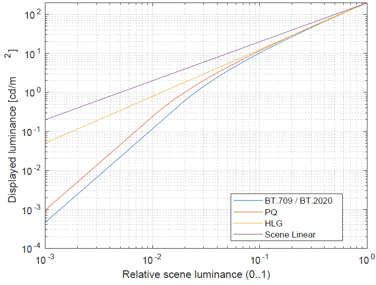
FIGURE A6-1 — OOTFs for the SDR and HDR formats compared to scene light
图 A6-1. SDR 与 HDR 各格式的 OOTF 与场景光的比较。
A6.1 Differences in chromaticity and saturation
A6.1 色品与饱和度的差异
Colours may be characterized by their chromaticity, which is the property of colour that is independent of luminance. To visualize chromaticity and chromaticity differences, the CIE 1976 uniform chromaticity scale diagram with chromaticity coordinates u’ and v’ may be used [17]. Each point in the diagram can be described either directly by its coordinates, or indirectly by its hue (or hue angle) and saturation.
色彩可由其色品来刻画,色品是色彩中与亮度无关的属性。为把色品及色品差异可视化,可使用带色品坐标 u′ 和 v′ 的 CIE 1976 均匀色品标度图 [17]。图中每个点既可直接用其坐标描述,也可间接用其色相(或色相角)和饱和度描述。
The hue (angle) is defined as huv = arctan[(v’ − v’n)/(u’ − u’n)] and the saturation as suv = 13 [(u’ − u’n)2 + (v’ − v’n)2]1/2 where u’n and v’n are the coordinates of the white point, which for television is CIE D65 with coordinates (0.1978, 0.4683). Thus, the saturation corresponds to the Euclidian distance from the white point.
色相(角)定义为 h_uv = arctan[(v′ − v′_n)/(u′ − u′_n)],饱和度定义为 s_uv = 13·[(u′ − u′_n)² + (v′ − v′_n)²]^(1/2),其中 u′_n 和 v′_n 为白点坐标——对电视而言为 CIE D65,坐标 (0.1978, 0.4683)。因此,饱和度对应于到白点的欧氏距离。
$$
h_{uv} = \arctan\!\left(\frac{v’ - v’_n}{u’ - u’n}\right),\qquad s{uv} = 13\left[(u’ - u’_n)^2 + (v’ - v’_n)^2\right]^{1/2}
$$
The uniform chromaticity diagram in Fig. A6-2 shows the display light colour swatch chromaticity for the different production formats. It can be observed that the colour swatch chromaticity for the different production formats falls approximately on a line of constant hue. Therefore, the chromaticity differences can substantially be characterized as saturation differences.
图 A6-2 的均匀色品图给出各制作格式显示光色块的色品。可以看出,不同制作格式的色块色品大致落在一条等色相线上。因此,色品差异基本上可刻画为饱和度差异。
It can be observed that BT.2020 generally provides the highest saturation while, by design, HLG provides the lowest saturation. This can also be observed from the saturation values shown in Fig. A6-3. The saturation differences with BT.709 are shown in Fig. A6-4 and the saturation differences with BT.2020 are shown in Fig. A6-5.
可以看出,BT.2020 总体上提供最高的饱和度,而 HLG 按设计提供最低的饱和度。这也可从图 A6-3 所示的饱和度值看出。与 BT.709 的饱和度差异见图 A6-4,与 BT.2020 的饱和度差异见图 A6-5。
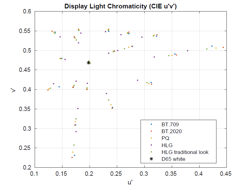
FIGURE A6-2 — Display light colour swatch chromaticity for the different production formats
图 A6-2. 各制作格式显示光色块的色品。
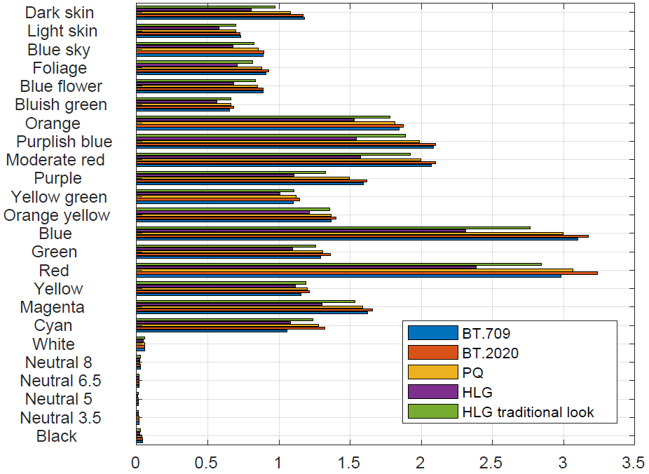
FIGURE A6-3 — Display light colour swatch saturation
图 A6-3. 显示光色块的饱和度。
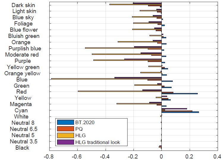
FIGURE A6-4 — Display light colour swatch saturation differences with BT.709
图 A6-4. 显示光色块与 BT.709 的饱和度差异。
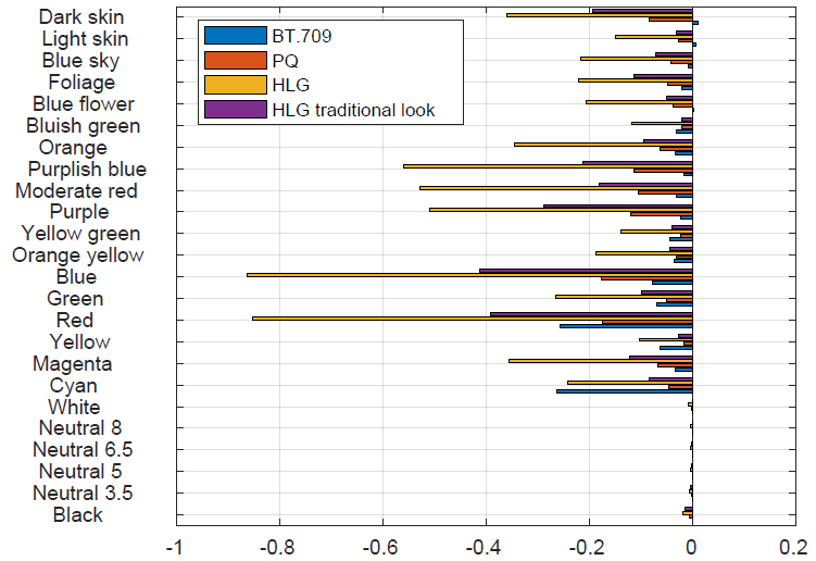
FIGURE A6-5 — Display light colour swatch saturation differences with BT.2020
图 A6-5. 显示光色块与 BT.2020 的饱和度差异。
A6.2 Quantifying the total colour differences
A6.2 量化总色差
While the differences in chromaticity and saturation of the colour swatches were shown in § A6.1, those differences do not take into account the luminance differences between the swatches and therefore do not represent the total colour differences. To quantify the total differences, a metric should be applied that takes into account the chromaticity differences as well as the luminance differences, such as e.g. the Delta E2000 metric defined by the CIE [19], or the new Delta EITP metric defined in Recommendation ITU-R BT.2124. The latter metric is applied in the following, using either the BT.709 or BT.2020 display light colour swatches as a reference.
A6.1 节给出了色块色品和饱和度的差异,但那些差异未计入色块之间的亮度差异,因此并不代表总色差。为量化总差异,应采用同时计入色品差异和亮度差异的度量,例如 CIE 定义的 Delta E2000 度量 [19],或建议书 ITU-R BT.2124 定义的新度量 Delta E_ITP。下文采用后者,分别以 BT.709 或 BT.2020 的显示光色块为参照。
The Delta EITP differences with BT.709 are shown in Fig. A6-6 and those with BT.2020 are shown in Fig. A6-7. It can be observed, e.g. that the differences for the highly saturated colours (such as Red and Blue) are larger than the differences with BT.709.
与 BT.709 的 Delta E_ITP 差异见图 A6-6,与 BT.2020 的见图 A6-7。例如可以看出,高饱和色彩(如红色和蓝色)的差异大于与 BT.709 的差异。
Note also the differences for the White/Neutral/Black colour swatches, which are luminance differences caused by the differences between the SDR and HDR OOTFs (as shown in Fig. A6-1). The relatively darker/lower scene luminances are displayed brighter in the HDR formats than in the SDR formats (so the HDR formats show/preserve additional detail in the dark).
还应注意白/中性/黑色块的差异,它们是由 SDR 与 HDR OOTF 之间的差异所造成的亮度差异(如图 A6-1 所示)。相对较暗/较低的场景亮度,在 HDR 格式中比在 SDR 格式中显示得更亮(因此 HDR 格式呈现/保留了暗部的额外细节)。
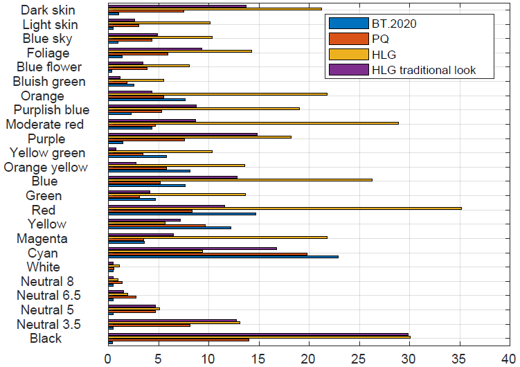
FIGURE A6-6 — Display light colour swatch Delta EITP with BT.709
图 A6-6. 显示光色块与 BT.709 的 Delta E_ITP。
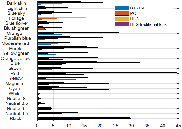
FIGURE A6-7 — Display light colour swatch Delta EITP with BT.2020
图 A6-7. 显示光色块与 BT.2020 的 Delta E_ITP。
A6.3 Comparison with the reference colour pattern data
A6.3 与参考色彩图案数据的比较
Instead of using one of the production formats as a reference for comparison, the original colour pattern reference data [16] can be used as well. To do so, the reference data is linearly scaled (i.e. a linear OOTF is applied) such that the white swatch luminance is approximately 200 cd/m2 as for the other formats.
除了以某种制作格式作为比较参照外,也可使用原始色彩图案参考数据 [16]。为此,对参考数据作线性缩放(即施加线性 OOTF),使白色块亮度如其他格式那样约为 200 cd/m²。
The saturation differences with the scaled colour pattern reference data are shown in Fig. A6-8. For the HLG format, the saturation differences are all 0, because the HLG format preserves the chromaticity (and therefore the saturation) of the scene as imaged by the camera. Note that this does not imply that the HLG format preserves the chromaticity of the original scene, since camera image adjustments, such as white balancing, will change the chromaticity.
与经缩放的色彩图案参考数据的饱和度差异见图 A6-8。对 HLG 格式,饱和度差异全为 0,因为 HLG 格式保留了相机所成场景的色品(因而也保留了饱和度)。需要注意,这并不意味着 HLG 格式保留了原始场景的色品,因为白平衡等相机图像调整会改变色品。
The Delta EITP differences with the scaled reference data are shown in Fig. A6-9. For the HLG format, the differences are purely luminance differences, caused by the difference between the relative scene luminances (linear OOTF) and the displayed luminances for the HLG format (OOTF gamma 1.2).
与经缩放参考数据的 Delta E_ITP 差异见图 A6-9。对 HLG 格式,这些差异纯粹是亮度差异,由相对场景亮度(线性 OOTF)与 HLG 格式显示亮度(OOTF 伽马 1.2)之间的差异所造成。
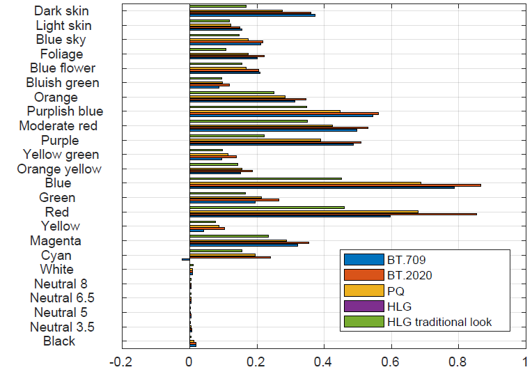
FIGURE A6-8 — Display light colour swatch saturation differences with the reference colour pattern
图 A6-8. 显示光色块与参考色彩图案的饱和度差异。
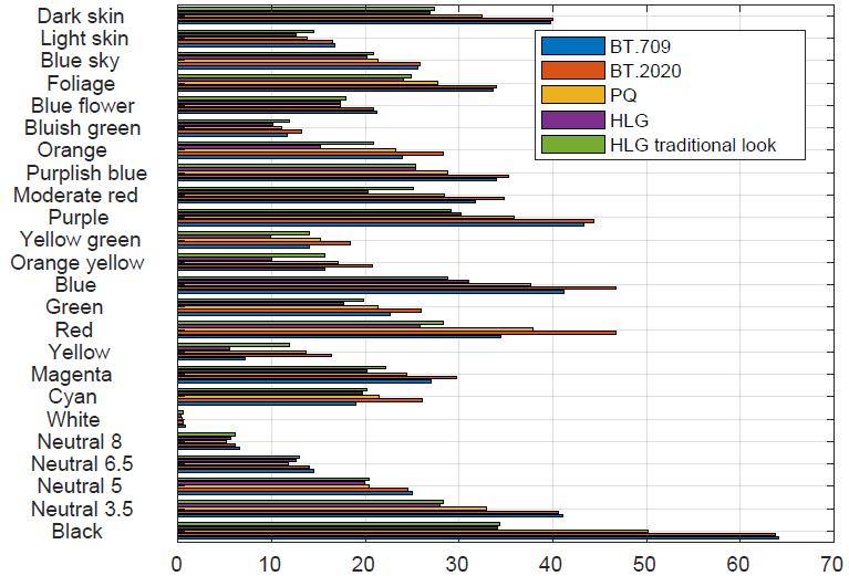
FIGURE A6-9 — Display light colour swatch Delta EITP with the scaled reference colour pattern
图 A6-9. 显示光色块与经缩放参考色彩图案的 Delta E_ITP。
附件 7 — 归一化基色矩阵的计算
Annex 7 — Calculating the normalized primary matrix
The normalized primary matrix is needed for the conversion process to and from the CIE XYZ colour space and the BT.2100 colour space, as described in § 8.
如第 8 节所述,在 CIE XYZ 色彩空间与 BT.2100 色彩空间之间相互转换的过程都需要归一化基色矩阵。
Camera and display systems are commonly defined by their normalized primary matrix, NPM, which is specified as follows:
相机和显示系统通常由其归一化基色矩阵(NPM)来定义,规定如下:
where the elements of the matrix depend on the chromaticity coordinates, (xR, yR), (xG, yG), (xB, yB), and (xW, yW) for red, green, blue, and white, respectively, that characterize each system.
式中矩阵各元素取决于刻画各系统特征的色度坐标,即红、绿、蓝、白分别对应的 (x_R, y_R)、(x_G, y_G)、(x_B, y_B) 和 (x_W, y_W)。
The NPM is needed for the conversion process to and from the CIE XYZ colour space and the BT.2100 colour space. Its elements could be computed as follows: First, compute the z coordinates for all colour primaries as follows:
NPM 用于在 CIE XYZ 色彩空间与 BT.2100 色彩空间之间相互转换。其各元素可如下计算:首先,按下式计算各基色的 z 坐标:
Then the matrix elements of NPM are derived as follows:
然后,NPM 的各矩阵元素按下式导出(式 6—14;为简洁,下面三组共用同一分母
All the chromaticity values for R, G, B, and White are defined in three or four decimal digits in ITU-R texts, from which the transformation matrices or NPMs are derived. All values shown in the matrices below were calculated with high precision and then rounded to four decimal digits. Matrix calculations should be performed using high precision coefficient values without rounding.
R、G、B 和白的所有色度值在 ITU-R 文本中均以三位或四位小数定义,转换矩阵或 NPM 即由其导出。下面各矩阵中所示的全部数值均以高精度计算后舍入到四位小数。矩阵计算应使用高精度系数值进行,不作舍入。
A7.1 Conversion of normalized linear colour signals to Recommendation ITU-R BT.2100
A7.1 把归一化线性颜色信号转换到建议书 ITU-R BT.2100
In the case for conversion to the BT.2100 colour space, where the source colour space is linear, normalized within the [0:1] range, and defined by a particular NPM, conversion can be done as follows:
当转换到 BT.2100 色彩空间、且源色彩空间为线性、在 [0, 1] 范围内归一化、并由某特定 NPM 定义时,可如下转换:
$$
$$
and:
即:
$$
$$
Finally, since not all colours in the source representation may be within the BT.2100 representation, an additional clipping process may be performed. The negative values may be clipped to zero. The positive values may also be clipped to the capabilities of the interface. Although both soft or hard clipping could be performed (see Report ITU-R BT.2407, in many applications hard clipping is preferred. In the scenario that hard clipping of only the negative values is performed the process would be as follows:
最后,由于源表示中并非所有色彩都落在 BT.2100 表示之内,可再作一道削波处理。负值可削到零;正值也可削到接口的能力上限。虽然软削波和硬削波皆可(见报告 ITU-R BT.2407),但在许多应用中更倾向于硬削波。若只对负值作硬削波,则处理如下:
The above transformations could be applied in both display and scene referred workflows. The conversion process, assuming a display referred camera workflow, as well as the final conversion to a BT.2100 representation, is shown in Fig. A7-1. For conversion to HLG, a bridge point of 1 000 cd/m2 is assumed, and can therefore use the reference OOTF (see § 6.2 of Report ITU-R BT.2390).
上述转换在显示参考和场景参考两种工作流中均可应用。假定采用显示参考相机工作流的转换过程,以及最终转换到 BT.2100 表示的过程,见图 A7-1。转换到 HLG 时,假定以 1 000 cd/m² 为桥接点,因而可使用参考 OOTF(见报告 ITU-R BT.2390 第 6.2 节)。
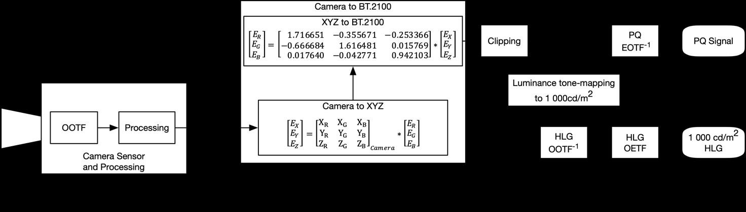
FIGURE A7-1 — Conversion of arbitrary display referred linear light signals to BT.2100 signals using a display referred workflow
图 A7-1. 用显示参考工作流把任意显示参考线性光信号转换为 BT.2100 信号。
Figure A7-2 depicts the conversion process when applied on a scene referred workflow with the BT.2100 HLG signal as its output. Figure A7-3 depicts the same conversion process when applied on a scene referred workflow with the BT.2100 PQ signal as its output.
图 A7-2 描绘在场景参考工作流中、以 BT.2100 HLG 信号为输出时的转换过程。图 A7-3 描绘同一转换过程在场景参考工作流中、以 BT.2100 PQ 信号为输出时的情形。

FIGURE A7-2 — Conversion of arbitrary scene referred light signals to a BT.2100 HLG signal using a scene referred workflow
图 A7-2. 用场景参考工作流把任意场景参考光信号转换为 BT.2100 HLG 信号。
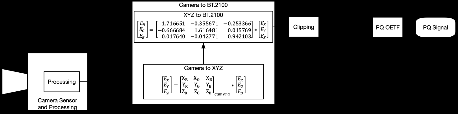
FIGURE A7-3 — Conversion of arbitrary scene referred light signals to a BT.2100 PQ signal using a scene referred workflow
图 A7-3. 用场景参考工作流把任意场景参考光信号转换为 BT.2100 PQ 信号。
A7.2 Conversion of BT.2100 to arbitrary linear colour signals for display systems
A7.2 把 BT.2100 转换为显示系统的任意线性颜色信号
Similarly, conversion from linear and normalized BT.2100 RGB primaries to the RGB primaries of an arbitrary display system can be performed as follows:
类似地,从线性且归一化的 BT.2100 RGB 基色转换为任意显示系统的 RGB 基色,可如下进行:
$$
$$
and:
即:
$$
$$
Not all colours in the original representation may be within the target representation. The negative values may be clipped to zero. The positive values may also be clipped to the capabilities of the display. Although both soft or hard clipping could be performed, in many applications, such as when using a reference display, hard clipping is preferred. In the scenario that hard clipping of only the negative values is performed the process would be as follows:
原表示中并非所有色彩都落在目标表示之内。负值可削到零;正值也可削到显示设备的能力上限。虽然软削波和硬削波皆可,但在许多应用中(如使用参考显示设备时)更倾向于硬削波。若只对负值作硬削波,则处理如下:
Figure A7-4 depicts this conversion process assuming a display referred workflow for both PQ and HLG. For conversion from HLG, the nominal peak luminance of the target display (and the appropriate system gamma) is used for the HLG OOTF.
图 A7-4 描绘在假定显示参考工作流下、针对 PQ 和 HLG 两者的这一转换过程。从 HLG 转换时,HLG OOTF 采用目标显示设备的标称峰值亮度(及相应的系统伽马)。
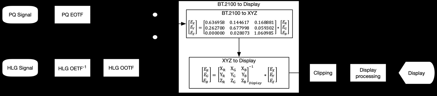
FIGURE A7-4 — Conversion of BT.2100 signals to an arbitrary display using a display referred workflow
图 A7-4. 用显示参考工作流把 BT.2100 信号转换到任意显示设备。
附件 8 — 中国的 4K/8K UHD HDR 与 HD SDR 同制同播实践
Annex 8 — 4K/8K UHD HDR and HD SDR simul-production and simulcast practice in China
A8.1 Background
A8.1 背景
It has become a focus of recent research as how to use UHD system to produce both UHD (Ultra High Definition) and HD (High Definition) at the same time, along with the transition from HD to UHD in media production and the broadcasting industry.
随着媒体制作和广播行业从 HD 向 UHD 过渡,如何用 UHD 系统同时制作 UHD(超高清)和 HD(高清),已成为近期研究的一个焦点。
The practice of CMG7 UHD and HD simultaneous broadcasting (hereinafter referred to as ‘simulcasting’) began in 2018. After the launch of the first 4K channel in China, CMG attempted simulcast of certain sports events and public events. In the live broadcast of the celebration of the 70th Anniversary of the National Day in 2019, CMG carried out 4K HDR production and simulcasting on a large scale.
中央广播电视总台(CMG)[7]的 UHD 与 HD 同时播出(以下简称“同播”)实践始于 2018 年。继中国开通首个 4K 频道后,CMG 对部分体育赛事和公共活动尝试了同播。在 2019 年庆祝国庆 70 周年的直播中,CMG 大规模开展了 4K HDR 制作和同播。
During the 2021 Spring Festival Gala, great experience was gained on 8K, 4K, HD simulcast. The Olympic UHD and HD Channels simulcast with the same content. To ensure this, CMG has summarized the practical experience of simulcast in recent years, released a set of relevant technical specifications, expanded relevant evaluation and research, and formed complete technical guidance for CMG simulcast.
在 2021 年春节联欢晚会中,积累了 8K、4K、HD 同播的丰富经验。奥运 UHD 与 HD 频道以相同内容同播。为保障这一点,CMG 总结了近年来同播的实践经验,发布了一套相关技术规范,扩展了相关评测和研究,形成了 CMG 同播的完整技术指导。
A8.2 Basic workflows and principles
A8.2 基本工作流与原则
The UHD signal format of CMG is required to be 4K HLG HDR, 3840x2160/50/P or 8K HLG HDR, 7680x4320/50/P, BT.2020; and HD signal format is required to be SDR, 1920x1080/50/I, BT.709. CMG simulcast requires 4K/8K HLG HDR production. HD specifications should be taken into consideration in the production process, and signals would be down-converted at the broadcasting end.
CMG 要求 UHD 信号格式为 4K HLG HDR(3840×2160/50/P)或 8K HLG HDR(7680×4320/50/P),BT.2020;HD 信号格式要求为 SDR(1920×1080/50/I),BT.709。CMG 同播要求采用 4K/8K HLG HDR 制作。制作过程中应顾及 HD 规格,信号在播出端下变换。
The production and broadcast workflow of recorded programmes is as follows: HD SDR shading is adopted in the pre-production process, with 4K/8K HDR files recorded. For HD signals or materials, up-conversion should be completed before they are inputted into the production system.
录制节目的制作与播出工作流如下:前期制作过程采用 HD SDR 明暗控制,录制 4K/8K HDR 文件。对 HD 信号或素材,应在输入制作系统之前完成上变换。
During the post-production process, only a 4K/8K HLG HDR version will be made, with proper reference to down-conversion at fixed mapping to HD. The final programme files will be transferred into the MAMS (media assets management system) for broadcast.
后期制作过程只制作一个 4K/8K HLG HDR 版本,并适当参考以固定映射下变换到 HD 的结果。最终节目文件转入媒体资产管理系统(MAMS)以供播出。
The UHD channels will be broadcast directly from the MAMS. For HD channels, there are two solutions: one is to use UHD channel signals at the broadcasting end, down-converting to HD signals with fixed mapping (see Fig. A8-1); the other is to use files transcoded using dynamic down-conversion in the MAMS to broadcast (see Fig. A8-2). Dynamic down-conversion is based on global brightness equilibrium analysis.
UHD 频道直接从 MAMS 播出。HD 频道有两种方案:一是在播出端使用 UHD 频道信号,以固定映射下变换为 HD 信号(见图 A8-1);二是使用在 MAMS 中以动态下变换转码所得的文件播出(见图 A8-2)。动态下变换基于全局亮度平衡分析。
The production and broadcast workflow of live broadcast programmes is as follows: SDR shading is adopted in pre-production. HD signals or materials should be up-converted before entering into the production system. The finished 4K/8K HLG HDR programmes are directly used for broadcasting in UHD channels. The broadcasting signals of HD channels are down-converted from UHD channel signals at the broadcasting end (see Fig. A8-3).
直播节目的制作与播出工作流如下:前期采用 SDR 明暗控制。HD 信号或素材应在进入制作系统之前作上变换。制作完成的 4K/8K HLG HDR 节目直接用于 UHD 频道播出。HD 频道的播出信号在播出端由 UHD 频道信号下变换而来(见图 A8-3)。
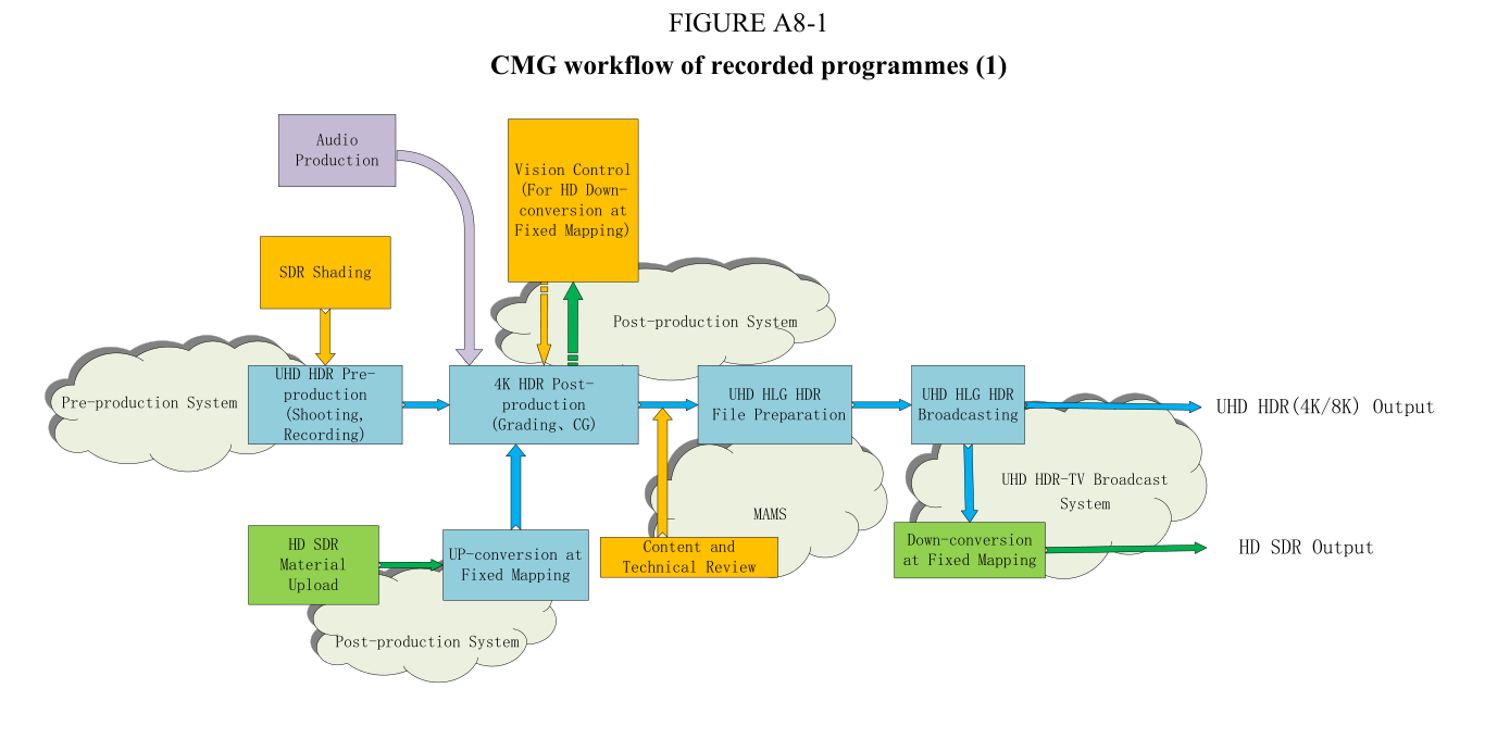
FIGURE A8-1 — CMG workflow of recorded programmes (1)
图 A8-1. CMG 录制节目工作流(一)。
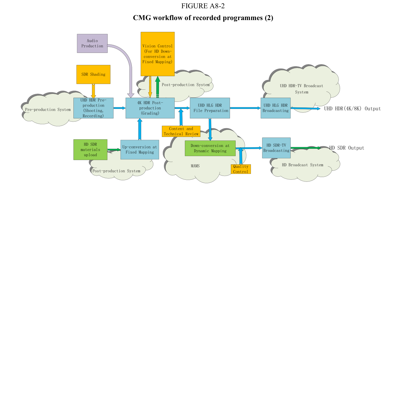
FIGURE A8-2 — CMG workflow of recorded programmes (2)
图 A8-2. CMG 录制节目工作流(二)。
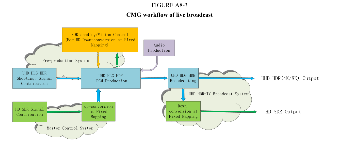
FIGURE A8-3 — CMG workflow of live broadcast
图 A8-3. CMG 直播工作流。
Programme production is implemented based on HLG 1 000 cd/m2. Considering the colour and saturation changes of images in conversion as well as comparing to actual shooting, CMG standardizes the ‘look’ of HDR images, based on which CMG then specifies the camera settings, up-converter settings and the corresponding LUTs. Furthermore, the style of down-conversion is defined with the corresponding LUTs and converter settings.
节目制作基于 HLG 1 000 cd/m² 进行。考虑到图像在转换中色彩和饱和度的变化、并与实际拍摄相比较,CMG 把 HDR 图像的“观感”加以标准化,并据此规定相机设置、上变换器设置及相应的 LUT。此外,还以相应的 LUT 和转换器设置来定义下变换的风格。
A8.3 Introduction of related work and research
A8.3 相关工作与研究简介
The evaluation and research work is carried out around UHD and HD simulcast, mainly focusing on HDR production, workflows verification and establishment, HDR-SDR mapping and conversion, camera related research, converter related research, LUT research and testing, etc. At the same time, lighting is also included in the research.
评测和研究工作围绕 UHD 与 HD 同播展开,主要聚焦于 HDR 制作、工作流的验证与建立、HDR-SDR 映射与转换、相机相关研究、转换器相关研究、LUT 研究与测试等。同时,照明也纳入了研究范围。
As a result of the above works, the correctness and implementability of the technical specifications have been verified; the production method of 4K/8K HDR has been defined; the simulcast workflow has been formed; the relevant parameter settings have been specified; and the CMG simulcast system has been established. The primary research work is focused on the following aspects:
(1) Two methods of production in 4K/8K HLG HDR system
(2) Analysis of mapping relation between HLG and SDR conversion
(3) Skin tone analysis
(4) Comparison between 4K/8K cameras and HD cameras
(5) Comparison of studio 4K/8K cameras of different manufacturers
(6) Converter usage and comparison of different manufacturers
(7) Influence of ‘knee’ on cameras and converters
(8) Parameter settings of cameras and converters
(9) CMG LUTs development and testing
(10) Research on scene light reference (SR) and display light reference (DR) in HDR-SDR conversion
(11) Influence of lighting characters on scene colour and skin tone
(12) Illuminance range of scene lighting under the ultimate aperture
(13) Ra, TLCI and SPD of commonly used studio lighting
上述工作使技术规范的正确性和可实施性得到验证;定义了 4K/8K HDR 的制作方法;形成了同播工作流;规定了相关参数设置;建立了 CMG 同播系统。主要研究工作集中在以下方面:
- 4K/8K HLG HDR 系统的两种制作方法;
- HLG 与 SDR 转换之间映射关系的分析;
- 肤色分析;
- 4K/8K 相机与 HD 相机的比较;
- 不同厂商演播室 4K/8K 相机的比较;
- 不同厂商转换器的使用与比较;
- “拐点”对相机和转换器的影响;
- 相机和转换器的参数设置;
- CMG LUT 的开发与测试;
- HDR-SDR 转换中场景光参考(SR)与显示光参考(DR)的研究;
- 照明特性对场景色彩和肤色的影响;
- 极限光圈下场景照明的照度范围;
- 常用演播室照明的 Ra、TLCI 和 SPD。
A8.4 Mapping for conversion between HDR and SDR
A8.4 HDR 与 SDR 之间的转换映射
In CMGʼs simulcast production, the mapping between HDR and SDR is 75%HLG-90%SDR. This mapping is also used in SDR shading. Tables A8-1 and A8-2 show the mapping between signal levels.
在 CMG 的同播制作中,HDR 与 SDR 之间的映射为 75%HLG–90%SDR。该映射也用于 SDR 明暗控制。表 A8-1 和表 A8-2 给出信号电平之间的映射。
表 A8-1. HLG-SDR 信号电平映射
| HLG 信号电平(IRE) | HLG 显示亮度 cd/m²(1 000 cd/m² 监视器) | SDR 信号电平(IRE) |
|---|---|---|
| 0 | 0 | 0 |
| 40 | 29.7 | 40 |
| 75 | 203 | 90 |
| 79 | 260 | 100 |
| 100 | 1000 | 109 |
注——SDR 信号电平是在拐点关闭(OFF)时测得的。
表 A8-2. SDR-HLG 信号电平映射
| SDR 信号电平(IRE) | HLG 信号电平(IRE) | HLG 显示亮度 cd/m²(1 000 cd/m² 监视器) |
|---|---|---|
| 0 | 0 | 0 |
| 40 | 40 | 29.7 |
| 90 | 75 | 203 |
| 100 | 79 | 260 |
| 109 | 82.5 | 324 |
注——SDR 信号电平是在拐点关闭(OFF)时测得的。
A8.5 Parameter settings
A8.5 参数设置
In order to ensure the CMG simulcast meets image requirements, settings of parameters for cameras and converters have been specified through objective tests and subjective assessments. Corresponding parameter settings are provided for cameras of different manufacturers used by CMG.
为确保 CMG 同播满足图像要求,通过客观测试和主观评估规定了相机和转换器的参数设置。针对 CMG 所用不同厂商的相机,提供了相应的参数设置。
In actual shooting, cameras need to be set according to specified parameters to achieve similar image perception as far as possible (see Fig. A8-4). For SDR materials or signals to be converted, if the converter used cannot load LUTs, the specified parameters should be used for conversion. In the similar down-conversion process, 4K/8K HDR signals need to be down-converted according to the specified parameters for HD broadcast or recording. In the past two years, these parameter settings have been continuously optimized in practice.
实际拍摄中,相机需按规定参数设置,以尽量获得相近的图像感受(见图 A8-4)。对待转换的 SDR 素材或信号,若所用转换器无法加载 LUT,则应使用规定参数进行转换。在相应的下变换过程中,4K/8K HDR 信号需按规定参数下变换,以供 HD 播出或录制。过去两年里,这些参数设置在实践中持续优化。
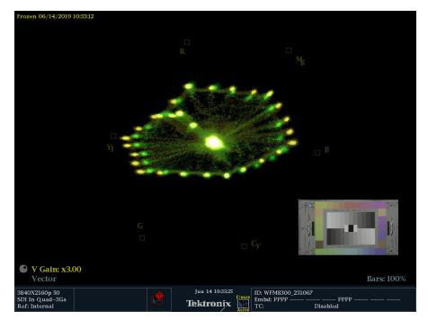
FIGURE A8-4 — Comparison of vector images taken by cameras of different manufacturers according to required parameter settings
图 A8-4. 不同厂商相机按要求参数设置所拍矢量图的比较。
A8.6 Converter performance consistency (LUTs usage)
A8.6 转换器性能一致性(LUT 的使用)
In the current workflow, the HDR/SDR converters play an important role. But converters of different models perform differently in terms of levels, hue, saturation, image look, etc. During the conversion process, it is impossible to exhaust the parameter settings of each model by subjectively and objectively comparing the brightness and colour consistency. It is also difficult to achieve consistency of the conversion style between different devices. To solve this, CMG LUT sets have been developed for different converters.
在当前工作流中,HDR/SDR 转换器扮演着重要角色。但不同型号的转换器在电平、色相、饱和度、图像观感等方面表现各异。转换过程中,靠主客观比较亮度和色彩一致性来穷举每个型号的参数设置是不可能的,不同设备之间转换风格的一致也难以实现。为解决这一问题,针对不同转换器开发了 CMG LUT 集。
LUT sets version 1 comprises 33 Cube 3D LUTs, including four sets as follows:
• HLG Scene light reference (SR) up-conversion
• HLG Scene light reference (SR) down-conversion
• HLG LIVE and HLG Native conversion
• Graphics signal conversion
第 1 版 LUT 集包含 33 个 Cube 3D LUT,分为以下四组:
- HLG 场景光参考(SR)上变换;
- HLG 场景光参考(SR)下变换;
- HLG LIVE 与 HLG Native 转换;
- 图形信号转换。
LUTs are intended for LUT devices that process narrow-range video signals but operate over the full 10-bit signal range (0 to 1 023). There are two types for each set, one offers the headroom to process super-whites, the other one is narrow-range. For SDR graphic signals, the mapping of up-conversion is 77%HLG-100%SDR, using display light reference (DR). For the rest, the mapping of up- or down-conversion of signals or materials is 75%HLG-90%SDR.
这些 LUT 面向处理窄范围视频信号、但在完整 10 比特信号范围(0 至 1 023)内工作的 LUT 设备。每组有两种类型,一种留有处理超白的余量,另一种为窄范围。对 SDR 图形信号,上变换映射为 77%HLG–100%SDR,采用显示光参考(DR);其余情形下,信号或素材上、下变换的映射为 75%HLG–90%SDR。
CMG LUTs mainly fit the mapping curve of the converters with fixed mapping used by CMG master control and broadcasting system, to achieve similar mapping relationship and gamut (see Figs A8-5 and A8-6). Subsequent research and development is underway for more conversion models.
CMG LUT 主要拟合 CMG 总控与播出系统所用固定映射转换器的映射曲线,以实现相近的映射关系和色域(见图 A8-5 和图 A8-6)。针对更多转换模型的后续研发正在进行。
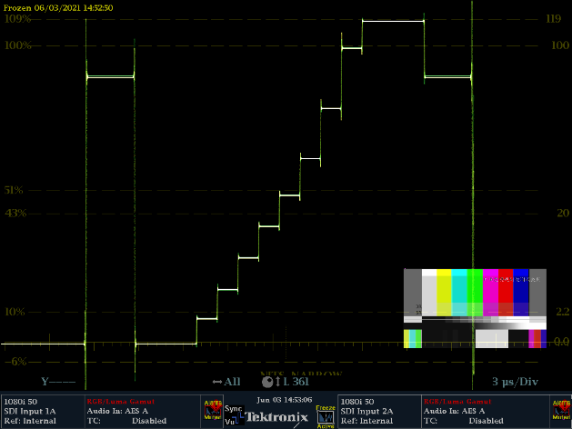
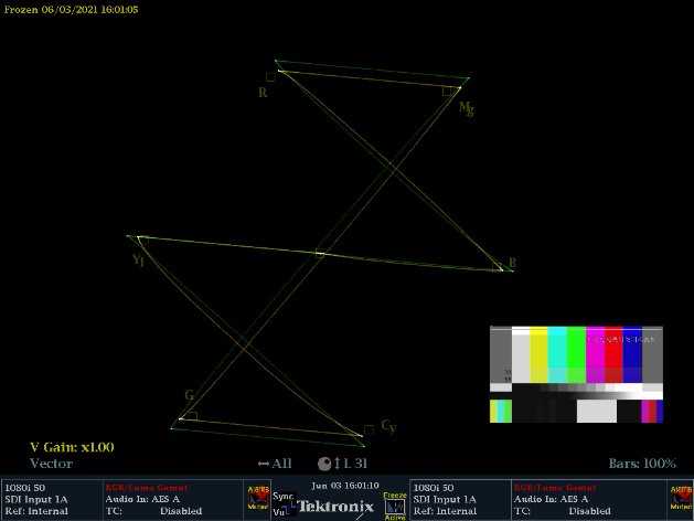
FIGURE A8-5 — Waveform and vector comparison between LUT and fixed parameter in down-conversion (Yellow line is the fixed parameter Converter)
图 A8-5. 下变换中 LUT 与固定参数的波形和矢量比较(黄线为固定参数转换器)。
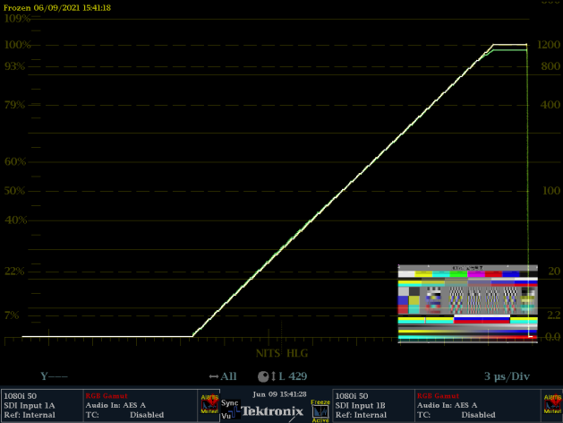
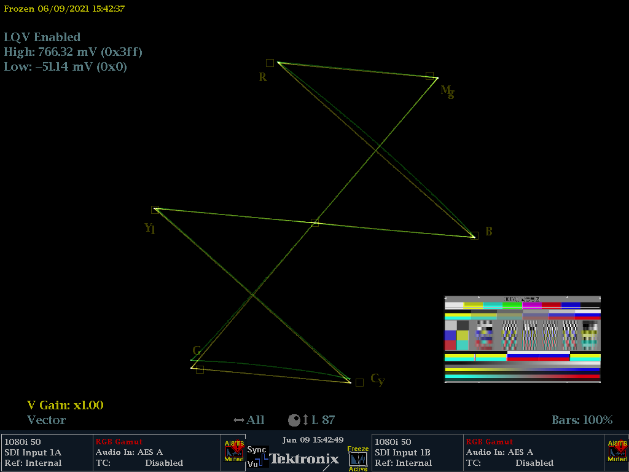
FIGURE A8-6 — Waveform and vector comparison between LUT and fixed parameter in down-conversion (Yellow line is the fixed parameter Converter)
图 A8-6. 下变换中 LUT 与固定参数的波形和矢量比较(黄线为固定参数转换器)。
A8.7 Signal range
A8.7 信号范围
Referring to § 2.4 of this Report, considering the CMG workflow and condition of devices, CMG recommends narrow range and super-white, no sub-black in the whole link. In the case of 10-bit digital coding, black level is 64, the nominal peak white level is 940, and super-white is 941-1023 (in the SDI system, super-white is 941-1019). For those devices that do not support super-white, CMG recommends clipping instead of mapping.
参照本报告 2.4 节,并考虑 CMG 工作流和设备条件,CMG 建议全链路采用窄范围加超白、不用次黑。在 10 比特数字编码下,黑位为 64,标称峰值白电平为 940,超白为 941–1023(在 SDI 系统中超白为 941–1019)。对不支持超白的设备,CMG 建议采用削波而非映射。
The use of super-white levels plays a great role in improving the dynamic range of HLG, especially on monitors and TV-sets with brightness over 1 000cd/m2 for UHD HDR production and display.
使用超白电平对提高 HLG 的动态范围作用很大,尤其在亮度超过 1 000 cd/m² 的监视器和电视机上进行 UHD HDR 制作和显示时。
A8.8 Consistency of international exchange
A8.8 国际交换的一致性
In the case of a recorded programme, the HDR programme will usually be subject to post-production, so consistency with requirements for interchange can be assured. For live feeds, there are several methods to ensure consistency: the first is to provide 4K HDR and HD SDR signals simultaneously, so there will not be any conversions; the second is to provide 4K HDR feeds together with fixed parameters (e.g. mapping relationship) for HDR to SDR conversion; the third is to use dynamic conversion, which is a recommended method to deal with the conversion.
对录制节目,HDR 节目通常要经过后期制作,因此可保证与交换要求的一致。对直播馈送,有几种确保一致的方法:第一是同时提供 4K HDR 与 HD SDR 信号,从而不存在任何转换;第二是在提供 4K HDR 馈送的同时,提供 HDR 到 SDR 转换的固定参数(如映射关系);第三是采用动态转换,这是处理转换的推荐方法。
A8.9 Summary
A8.9 小结
1 CMG defines the signal format, adopts HDR production for HDR/SDR simulcast and sets up the workflows for recorded programmes and live broadcast. Practice has proved that this simulcast facilitates the programme production and broadcasting efficiently, as well as guaranteeing the quality of both UHD and HD programmes.
2 CMG forms its own HDR image look, then defines the up- or down-conversion style, and furthermore specifies the mapping relation between HDR and SDR in simulcast.
3 Based on the relation between HDR and SDR in simulcast, CMG provides the parameter settings for cameras, HDR converter and corresponding LUTs.
- CMG 定义了信号格式,采用 HDR 制作来实现 HDR/SDR 同播,并建立了录制节目和直播的工作流。实践证明,这种同播高效地便利了节目制作和播出,同时保证了 UHD 和 HD 两种节目的质量。
- CMG 形成了自己的 HDR 图像观感,进而定义了上、下变换风格,并进一步规定了同播中 HDR 与 SDR 之间的映射关系。
- 基于同播中 HDR 与 SDR 的关系,CMG 为相机、HDR 转换器及相应 LUT 提供了参数设置。
附件 9 — 近距离并置的 HDR 与 SDR 监视器
Annex 9 — HDR and SDR monitors in close proximity
This Annex describes approaches to monitoring HDR and SDR in close proximity while avoiding eye adaptation issues.
本附件描述在近距离并置监看 HDR 与 SDR、同时避免眼睛适应问题的方法。
The order for the approaches described below should not be taken to indicate a preferred method. Approach A is used for side-by-side vision supervision, multiviews or where the control room HDR and SDR images are in close proximity. Approach B is used for side-by-side video shading, vision supervision, multiviews or where the control room HDR and SDR images are in close proximity.
下文所述方法的先后顺序不应被理解为表示优先取舍。方法 A 用于并排视频监督、多画面,或控制室 HDR 与 SDR 图像近距离并置的场合。方法 B 用于并排视频明暗控制、视频监督、多画面,或控制室 HDR 与 SDR 图像近距离并置的场合。
A9.1 Approach A: Matching SDR diffuse white level by adapting HDR monitor peak luminance
A9.1 方法 A:通过调整 HDR 监视器峰值亮度来匹配 SDR 漫反射白电平
Some broadcasters use Approach A where they have found that in some situations, for example within the confined space of an outside broadcast truck, it is not practicable to achieve complete separation between the SDR and HDR monitors in the control room.
一些广播机构采用方法 A,因为他们发现在某些情形下(例如转播车的狭小空间内),要在控制室中把 SDR 与 HDR 监视器完全分开并不现实。
Approach A sets critical SDR monitoring at a reference peak white luminance of 100 cd/m2, to avoid eye adaptation issues from an HDR monitor in close proximity that has a reference white which does not match. The nominal peak white luminance of the HLG HDR monitor can be lowered to reduce the disturbance, for example to 600 cd/m2 (in which case HDR Reference White is displayed at 138 cd/m2) with an appropriate system gamma adjustment, see § 3.2. This has the further advantage that a 1 000 cd/m2 monitor adjusted this way can usually display the HLG ‘super-white’ signal range. Approach A can also be used in the cases where there are complaints of eye-strain. Specific examples are described in Annexes 10 and 11.
方法 A 把关键 SDR 监看设在 100 cd/m² 的参考峰值白亮度,以避免近距离 HDR 监视器因参考白不匹配而引起的眼睛适应问题。可调低 HLG HDR 监视器的标称峰值白亮度以减少干扰,例如调到 600 cd/m²(此时 HDR 参考白显示为 138 cd/m²),并作相应的系统伽马调整,见 3.2 节。这样做还有一个好处:经此调整的 1 000 cd/m² 监视器通常能显示 HLG 的“超白”信号范围。方法 A 也可用于有人抱怨眼睛疲劳的情形。具体示例见附件 10 和附件 11。
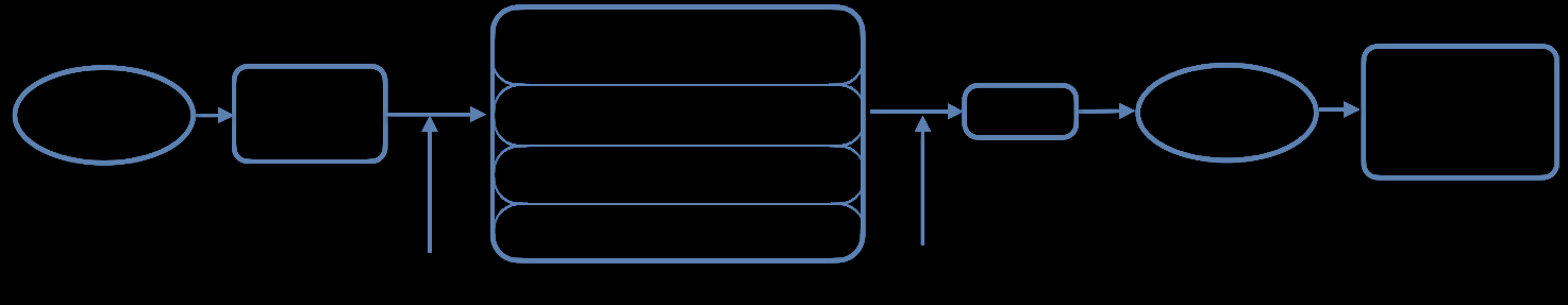
FIGURE A9-1 — Example signal flow – gamma-adjusted HDR-to-SDR conversion
图 A9-1. 信号流示例——经伽马调整的 HDR 到 SDR 转换。
The example signal flow of Approach A illustrated in Fig. A9-1 anchors HDR diffuse white level at approximately 100 cd/m2. The multiple elements for tone mapping (centre) can be ordered based on a designer’s preference. HLG-to-SDR conversion uses a gamma-adjusted display-light conversion. The SDR produced will be aligned to that of a conventional SDR production, as both are produced using 100 cd/m2 displays.
图 A9-1 所示方法 A 的信号流示例,把 HDR 漫反射白电平锚定在约 100 cd/m²。色调映射的多个环节(中部)可按设计者偏好排序。HLG 到 SDR 转换采用经伽马调整的显示光转换。所产生的 SDR 将与常规 SDR 制作对齐,因为两者都用 100 cd/m² 显示设备制作。
To achieve a consistent diffuse white level, this example uses an HLG display with a peak white luminance capability in a range between 300-600 cd/m2 which will produce a diffuse white luminance level of 79-138 cd/m2 at 75% HLG signal level based on its use of a slightly lower system gamma described in Recommendation ITU-R BT.2100. The relative nature of the HLG OOTF will scale the entire luminance range of the displayed image as designed and the luminance of the diffuse white level at 75% HLG signal level will follow.
为获得一致的漫反射白电平,本例使用峰值白亮度能力在 300–600 cd/m² 范围内的 HLG 显示设备;基于其采用建议书 ITU-R BT.2100 所述略低的系统伽马,它在 75% HLG 信号电平处会产生 79–138 cd/m² 的漫反射白亮度电平。HLG OOTF 的相对特性会按设计缩放所显示图像的整个亮度范围,75% HLG 信号电平处漫反射白的亮度也随之而定。
Broadcasters have the freedom to select their preferred SDR diffuse white level (or HDR to SDR conversion method) and adjust the HLG monitor peak luminance accordingly.
广播机构可自由选择其偏好的 SDR 漫反射白电平(或 HDR 到 SDR 转换方法),并相应调整 HLG 监视器的峰值亮度。
Experiments performed by Philips have shown that the range of 300-400 cd/m2 HLG monitor peak luminance enables the HDR reference white level (75% HLG) to match the SDR diffuse white level in the range of 91% to 100% SDR, or the range of 79 to 100 cd/m2 on a 100 cd/m2 peak luminance SDR monitor. By matching the HDR and SDR diffuse white levels, eye adaptation issues can be avoided in close proximity monitoring of HDR and SDR.
飞利浦所做的实验表明,HLG 监视器峰值亮度在 300–400 cd/m² 范围内时,可使 HDR 参考白电平(75% HLG)与 SDR 漫反射白电平相匹配——后者在 100 cd/m² 峰值亮度 SDR 监视器上为 91% 至 100% SDR,即 79 至 100 cd/m²。通过匹配 HDR 与 SDR 的漫反射白电平,可在近距离并置监看 HDR 与 SDR 时避免眼睛适应问题。
A9.2 Approach B: Matching HDR diffuse white level by adapting SDR monitor peak luminance
A9.2 方法 B:通过调整 SDR 监视器峰值亮度来匹配 HDR 漫反射白电平
Some broadcasters use Approach B where rather than decrease the nominal peak luminance of the HLG display, the nominal peak luminance of the nearby SDR display has been increased from 100 to 203 cd/m2 using the latitude described in Recommendation ITU-R BT.1886 and in Report ITU-R BT.2129. In this approach, rather than targeting BT.2035 requirements, a different HDR-to-SDR down-mapping produces an image that is subjectively similar to the HLG signal on a 203 cd/m2 BT.1886 SDR display whilst maintaining the HDR monitor at 1 000 cd/m2. Specific examples are described in Annex 10.
一些广播机构采用方法 B:不去降低 HLG 显示设备的标称峰值亮度,而是利用建议书 ITU-R BT.1886 和报告 ITU-R BT.2129 所述的余地,把邻近 SDR 显示设备的标称峰值亮度从 100 cd/m² 提高到 203 cd/m²。在此方法中,不以 BT.2035 要求为目标,而用一种不同的 HDR 到 SDR 下映射,产生一幅在主观上与 203 cd/m² BT.1886 SDR 显示设备上的 HLG 信号相近的图像,同时把 HDR 监视器保持在 1 000 cd/m²。具体示例见附件 10。
A9.2.1 Signal flow - hybrid-linear HDR-to-SDR conversion
A9.2.1 信号流——混合线性 HDR 到 SDR 转换
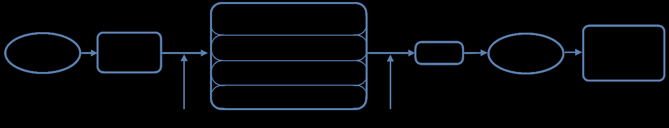
FIGURE A9-2 — Example signal flow - hybrid-linear HDR-to-SDR conversion
图 A9-2. 信号流示例——混合线性 HDR 到 SDR 转换。
In the example signal flow of Approach B illustrated in Fig. A9-2, the SDR display’s peak luminance (Lw) is adjusted to match the chosen HDR reference white of 203 cd/m2 using the existing gain (contrast) adjustment. The multiple elements for tone mapping (centre) can be ordered based on the designer’s preference. Recommendation ITU-R BT.1886 was designed with an adjustable peak white luminance using Lw (the contrast control) for a linear scaling factor of black to peak white.
在图 A9-2 所示方法 B 的信号流示例中,用现有的增益(对比度)调整,把 SDR 显示设备的峰值亮度(L_W)调到与所选的 203 cd/m² HDR 参考白相匹配。色调映射的多个环节(中部)可按设计者偏好排序。建议书 ITU-R BT.1886 在设计上允许用 L_W(对比度控制)调整峰值白亮度,以实现从黑到峰值白的线性缩放因子。
This example converts the HDR source using display-light conversion with a linear-scaling factor from HDR black to reference white which is followed by a subjective knee that typically begins close to reference white, compressing and attempting to preserve additional HDR highlight detail in the derived SDR.
本例用显示光转换来转换 HDR 源,从 HDR 黑到参考白采用线性缩放因子,其后接一个主观拐点(通常在接近参考白处开始),对所导出 SDR 中额外的 HDR 高光细节进行压缩并力求保留。
This example’s linear scaling factor for HDR-to-SDR down-mapping mimics Recommendation ITU-R BT.1886 and attempts to optimize the images for viewing SDR at 203 cd/m2. Typically higher luminance displays will closely match the HDR image levels from black to reference white when the transfer function of the SDR picture mode is similar to the Reference SDR EOTF from Recommendation ITU-R BT.1886.
本例用于 HDR 到 SDR 下映射的线性缩放因子模仿建议书 ITU-R BT.1886,力求为在 203 cd/m² 观看 SDR 而优化图像。当 SDR 画面模式的转换函数与建议书 ITU-R BT.1886 的参考 SDR EOTF 相近时,亮度较高的显示设备通常能在从黑到参考白的范围内与 HDR 图像电平紧密匹配。
附件 10 — NBCUniversal 的单母版 HDR-SDR 工作流
Annex 10 — NBCUniversal single-master HDR-SDR workflow
2020, the NBCU downstream production and public distribution in the US market has shown that the combination of 1 000 cd/m2 HLG display, 203 cd/m2 BT.1886 SDR display and proprietary LUTs [20] work well together for camera shading and simultaneous production and distribution of HDR in PQ and SDR:
– Paris, Tokyo, Beijing Olympics Live Broadcasts.
– Notre Dame Football beginning in 2022; Sunday Night Football beginning in 2023.
– The Saturday Night Live’s 50th Anniversary Music Special (2025) – Streaming on Peacock.
These productions use techniques defined in Recommendation ITU-R BT.2166 Method B.
自 2020 年以来,NBCU 在美国市场的下游制作与公共分发表明:1 000 cd/m² HLG 显示设备、203 cd/m² BT.1886 SDR 显示设备与专有 LUT [20] 三者配合,能很好地用于摄像机明暗控制,以及以 PQ 形式的 HDR 与 SDR 的同时制作和分发:
- 巴黎、东京、北京奥运会直播;
- 圣母大学橄榄球(2022 年起);周日晚橄榄球(2023 年起);
- 《周六夜现场》50 周年音乐特辑(2025 年)——在 Peacock 流媒体播出。
这些制作采用建议书 ITU-R BT.2166 方法 B 所定义的技术。
In this workflow, the ‘Hybrid-Linear’ down-mapper used to create the main SDR programme linearly scales the display-light signals in a similar manner to the BT.1886 reference EOTF for SDR. The result of the conversion produces a match between the original HDR images and the converted SDR images viewed on a BT.1886 SDR display (Gamma 2.4) with a non-reference peak luminance setting of 203 cd/m2 and an approximate match on a display that uses gamma 2.2, where there will be a slight shadow and midtone stretch (see Table A10-1). The roundtrip (SDR->HDR->SDR) is also designed to provide an excellent match. In both cases, original artistic intent is preserved because of optimal gain-staging of shadows, midtones and reference-white in the up and down-mappers.
在这一工作流中,用于生成主 SDR 节目的“混合线性”下映射器,以类似于 SDR 的 BT.1886 参考 EOTF 的方式线性缩放显示光信号。转换结果使原始 HDR 图像,与在峰值亮度设为非参考值 203 cd/m² 的 BT.1886 SDR 显示设备(伽马 2.4)上观看的转换 SDR 图像相匹配;在使用伽马 2.2 的显示设备上则近似匹配,此时暗部和中间调会略有拉伸(见表 A10-1)。往返(SDR→HDR→SDR)也经设计以提供极佳的匹配。两种情形下,由于在上、下映射器中对暗部、中间调和参考白作了最优的增益分级,原始艺术意图得以保留。
As described in § 7.1.4 on Camera Shading, both technical and perceptual line-up are used by shaders to achieve the desired look for final transmission.
如 7.1.4 节关于摄像机明暗控制所述,视频控制员同时使用技术校线和感知校线,以达到最终播出所需的观感。
In today’s workflows, the two most common down-mappers use very similar approaches which is anchored around diffuse white, but because of differences in gamma-adjusted versus hybrid-linear mappings, optimal images are achieved by matching the production and transmission down-mappers. Table A10-1 attempts to describe the perceptual results of best-practice versus the alternative.
在如今的工作流中,两种最常见的下映射器采用十分相似、以漫反射白为锚的做法,但由于伽马调整映射与混合线性映射之间的差异,只有让制作端与播出端的下映射器相匹配,才能获得最优图像。表 A10-1 试图描述最佳实践与其他做法的感知结果。
Technical and Perceptual line-up adjustments that affect camera exposure – Technical line-up based on HDR or SDR midtone levels are made so that the HDR camera exposures will match between multiple cameras and to make camera switching perceptually seamless. Technical and perceptual adjustments are affected by subtle midtone level differences in the gamma-adjusted or hybrid-linear LUTs which are described below.
a) Hybrid-Linear LUTs in production produce a slightly higher HDR camera exposure because shaders observe a linear mapping of the SDR signal optimized for a 203 cd/m2 display which does not include the shadow/midtone boost that is designed into the gamma-adjusted LUT. Without the shadow/midtone boost, shaders typically push the HDR camera exposure slightly higher.
b) Gamma-Adjusted LUTs in production produce a slightly lower HDR camera exposure because shaders perceive the higher average luminance produced by the slightly raised shadows and midtones needed to create a match between an HDR display and a 100 cd/m2 SDR reference display so that the exposure adjustment is slightly lowered.
c) In a typical production, it is common for the technical and perceptual adjustments to be made interactively as shaders fine-tune levels around fleshtones, grass and other focal elements while preserving their desired detail in the SDR scene at diffuse white. In both cases the LUTs are designed to work in pairs for roundtrip functionality.
影响相机曝光的技术校线与感知校线——基于 HDR 或 SDR 中间调电平进行技术校线,是为了让多台相机之间的 HDR 相机曝光相匹配,并使切换在感知上无缝。技术校线和感知校线受到伽马调整或混合线性 LUT 中细微中间调电平差异的影响,分述如下:
a) 制作中的混合线性 LUT 会产生略高的 HDR 相机曝光,因为视频控制员看到的是针对 203 cd/m² 显示设备优化的 SDR 信号线性映射,其中不含伽马调整 LUT 所内置的暗部/中间调提升。没有暗部/中间调提升,视频控制员通常会把 HDR 相机曝光推得略高。
b) 制作中的伽马调整 LUT 会产生略低的 HDR 相机曝光,因为视频控制员感受到的是:为在 HDR 显示设备与 100 cd/m² SDR 参考显示设备之间建立匹配而略微抬升暗部和中间调所产生的较高平均亮度,于是把曝光调整略微调低。
c) 在典型制作中,技术调整与感知调整常以交互方式进行:视频控制员围绕肤色、草地等焦点元素微调电平,同时在漫反射白处保留 SDR 场景中所需的细节。两种情形下,LUT 都设计为成对工作,以实现往返功能。
In Table A10-1, the NBCUniversal workflow is identified as “CASE #2”.
在表 A10-1 中,NBCUniversal 工作流标识为“案例 2(CASE #2)”。
表 A10-1. HDR 下映射方法的比较
TABLE A10-1 — Comparison of HDR down-mapping methods
(案例 1:伽马调整工作流;案例 2:建议书 ITU-R BT.2166 方法 B 下双重心工作流的观看条件;案例 3—6:不推荐——映射 LUT 不匹配。下文 “BT.1886/2035” 指建议书 ITU-R BT.1886 与 ITU-R BT.2035;“BT.1886/2129” 指建议书 ITU-R BT.1886 与报告 ITU-R BT.2129。)
| 项目 | 案例 1 | 案例 2 | 案例 3 | 案例 4 | 案例 5 | 案例 6 |
|---|---|---|---|---|---|---|
| A 下映射器与 SDR BT.1886 节目母版监看 | “伽马调整”,针对 100 cd/m² 优化(BT.1886/2035) | “混合线性”,针对 203 cd/m² 优化(BT.1886/2129) | “伽马调整”,针对 100 cd/m² 优化(BT.1886/2035) | “混合线性”,针对 203 cd/m² 优化(BT.1886/2129) | “混合线性”,100 cd/m²(BT.1886/2129) | “混合线性”,100 cd/m²(BT.1886/2129) |
| B SDR 播出下映射器 | “伽马调整”,针对 100 cd/m² 优化(BT.1886/2035) | “混合线性”,针对 203 cd/m² 优化(BT.1886/2129) | “混合线性”,针对 203 cd/m² 优化(BT.1886/2129) | “伽马调整”,针对 100 cd/m² 优化(BT.1886/2035) | “伽马调整”,针对 100 cd/m² 优化(BT.1886/2035) | “混合线性”,针对 203 cd/m² 优化(BT.1886/2129) |
| C SDR 播出,203 cd/m² BT.1886 显示 | 与制作中监看相同,SDR 往返观感得以保留 | SDR 暗部/中间调比制作中监看略暗 | SDR 暗部/中间调比制作中监看略暗 | SDR 暗部/中间调比制作中监看略亮 | SDR 暗部/中间调比制作中监看过亮 | 与制作中监看相同 |
| D HDR 播出观感 | SDR 暗部/中间调比制作中监看略亮 | 与制作中监看相同,SDR 往返观感得以保留 | 总体效果与 SDR 制作相近,高光压缩略有差异 | 中间调比制作中监看更亮 | SDR 更亮、对比度低于制作中监看,有削波风险 | SDR 暗部/中间调比制作中监看略亮 |
| E HDR 播出(相机曝光) | 曝光略低于案例 2 | 曝光略低于案例 1 | 同案例 1 | 同案例 2 | 相机曝光更高 | 相机曝光更高 |
HDR highlight preservation in converted SDR for both tone-mapping methods
There will be a slight level reduction above reference white down-mapped from HDR in order to preserve compressed HDR highlights in the converted SDR.
两种色调映射方法在转换所得 SDR 中对 HDR 高光的保留
为在转换所得的 SDR 中保留压缩后的 HDR 高光,由 HDR 下映射所得、高于参考白的部分电平会略有下调。
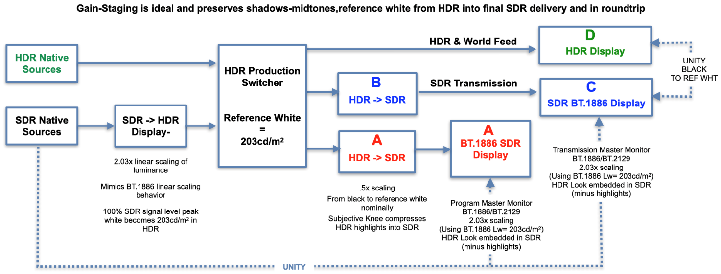
FIGURE A10-1 — Signal Flow –2× Linear Scaling with complementary ‘hybrid-linear’ down-mapper
图 A10-1. 信号流——2 倍线性缩放,配以互补的“混合线性”下映射器。
Grading an HDR distributed signal for downstream conversion optimized for 203 cd/m2 SDR viewing, produces slightly darker midtones when viewed on a 100 cd/m2 display based on BT.2035 recommendations but does preserve the artistic intent from the original HDR images.
把 HDR 分发信号调色、以供下游转换并针对 203 cd/m² SDR 观看优化,在基于 BT.2035 建议的 100 cd/m² 显示设备上观看时中间调会略暗,但确实保留了原始 HDR 图像的艺术意图。
A method of converting between the 203 cd/m2 SDR optimized content and 100 cd/m2 BT.2035 content for programme exchange is described in Annex 11. This conversion method can be used via prior agreement once the tone mapping methods and the responsibility for the conversion of HDR to SDR are discussed with the content creators.
在针对 203 cd/m² SDR 优化的内容与 100 cd/m² BT.2035 内容之间相互转换、以供节目交换的方法,见附件 11。一旦就色调映射方法以及 HDR 到 SDR 转换的责任与内容创作者商定,即可经事先约定使用这一转换方法。
The transforms used in this workflow can be found in “Single-Master” UHD-HDR-SDR Workflow [20].
本工作流所用的变换可在《“单母版”UHD-HDR-SDR 工作流》[20] 中找到。
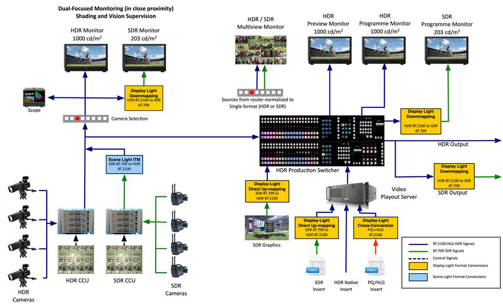
FIGURE A10-2 — NBCUniversal Single-Master HDR production with a dual-focused Shading and Vision Supervision
图 A10-2. NBCUniversal 采用双重心明暗控制与视频监督的单母版 HDR 制作。
In Fig. A10-2, HDR and 203 cd/m2 SDR displays can be placed side-by-side. Both the ‘Hybrid-Linear’ scaling method and the ‘gamma-adjusted’ method can be used for the down-mapping in TX(Transmission). ‘Hybrid-Linear’ content will be optimized for 203 cd/m2 SDR viewing (CASE #2) and ‘gamma-adjusted’ down mapping will be optimized for 100 cd/m2 SDR viewing (CASE #5). Please examine Table A10-1 to understand the perceptual effects in each use case.
• The HDR-to-SDR ‘Hybrid-Linear’ down-mapping LUT can be used as a ‘predictive LUT’ to preview the transmission rendering that matches the HDR very closely with the converted SDR when viewed on BT.1886 SDR displays set at 203 cd/m2 (minus highlights and some shadow detail).
• For the purposes of simplicity, both methods do not describe the complexities of the colour mapping or highlight compression (from HDR to SDR) which are based on subjective choices but can have a large impact on the preservation of detail when reducing the dynamic range from HDR to SDR.
在图 A10-2 中,HDR 显示设备与 203 cd/m² SDR 显示设备可并排放置。播出(TX)端的下映射既可用“混合线性”缩放法,也可用“伽马调整”法。“混合线性”内容将针对 203 cd/m² SDR 观看优化(案例 2),“伽马调整”下映射将针对 100 cd/m² SDR 观看优化(案例 5)。请参看表 A10-1 以理解各用例的感知效果。
- HDR 到 SDR 的“混合线性”下映射 LUT 可用作“预测 LUT”,以预览播出渲染——在设为 203 cd/m² 的 BT.1886 SDR 显示设备上观看时,它与 HDR 极为接近(除高光和部分暗部细节外)。
- 为简明起见,两种方法都未描述色彩映射或高光压缩(从 HDR 到 SDR)的复杂之处——它们基于主观选择,但在把动态范围从 HDR 缩减到 SDR 时,可能对细节保留有很大影响。
The ‘display-referred ’method of mapping SDR content into a Hybrid Log-Gamma (HLG) container, without an OOTF adjustment, is the preferred workflow when SDR material is converted using tone mapping optimized for 203 cd/m2 viewing. This method ensures minimal round-trip losses when combined with the down-mapper that matches the Linear up-mapping method (2.03× scaling factor).
当 SDR 素材采用针对 203 cd/m² 观看优化的色调映射进行转换时,把 SDR 内容映射进混合对数伽马(HLG)容器、不作 OOTF 调整的“显示参考”方法,是首选工作流。该方法与匹配线性上映射法(2.03× 缩放因子)的下映射器结合使用时,可确保往返损失最小。
A ‘Hybrid-Linear’ down-mapping (~0.5 scaling factor from black to reference white) will preserve the lowlights, midtones and HDR Reference White from the HDR to SDR conversion if the nominal SDR peak luminance of 203 cd/m2 is used. That is because the linear display light is scaled down to 100 cd/m2 and is then complemented by a linear scaling back to 203 cd/m2 in the SDR display itself. This usage is described in Recommendation ITU-R BT.1886 / Report ITU-R BT.2129 where a latitude of 100-250 cd/m2 for programme master monitoring is described.
若采用 203 cd/m² 的标称 SDR 峰值亮度,“混合线性”下映射(从黑到参考白约 0.5 的缩放因子)会在 HDR 到 SDR 转换中保留暗部、中间调和 HDR 参考白。这是因为线性显示光被缩小到 100 cd/m²,随后在 SDR 显示设备内本身又被线性缩放回 203 cd/m²,二者互补。这一用法在建议书 ITU-R BT.1886/报告 ITU-R BT.2129 中有所描述,其中给出了节目母版监看 100–250 cd/m² 的余地。
The ‘Hybrid-Linear’ down-mapper is an inverse of the direct-mapper (reversing the 2.03× linear scaling from SDR to HDR). It can be used as a ‘predictive’ for the look of the SDR transmission at 203 cd/m2. For this to be optimal, SDR displays should be switched to BT.1886 and set at a peak white luminance level of 203 cd/m2.
“混合线性”下映射器是直接映射器的逆(即逆转从 SDR 到 HDR 的 2.03× 线性缩放)。它可用作 203 cd/m² SDR 播出观感的“预测”。要使其最优,SDR 显示设备应切换到 BT.1886,并设为 203 cd/m² 的峰值白亮度电平。
Some broadcasters are using the ‘hybrid-linear’ down-mapping LUT with primary SDR shading displays set at 100 cd/m2 where the SDR displays and their vision supervisors are separated from the HDR displays to avoid eye adaption issues. In that instance, the subjective appearance of the shadows and midtones between HDR and SDR will not match even after adaption.
一些广播机构在使用“混合线性”下映射 LUT 时,把主 SDR 明暗控制显示设备设为 100 cd/m²,并把 SDR 显示设备及其视频主管与 HDR 显示设备分开,以避免眼睛适应问题。在这种情形下,即便经过适应,HDR 与 SDR 之间暗部和中间调的主观观感也不会匹配。
A table is provided with outcomes using five use-cases. Table A10-1 illustrates the effect of using different down-mapping methods in production and onward distribution.
本附件提供了一张涵盖若干用例结果的表。表 A10-1 说明了在制作和后续分发中采用不同下映射方法的效果。
Example of dynamic HDR to SDR tone mapping
Informal experiments by Philips have shown that SDR monitoring at 203 cd/m2 is also suitable to verify and demonstrate the performance of dynamic HDR to SDR conversion methods, since it enables a direct comparison between the HDR and SDR signals. Furthermore, by adding a second SDR monitor, the dynamic HDR to SDR conversion can also be compared directly to a static HDR to SDR conversion (LUT). Such a set-up is shown in Fig. A10-3.
动态 HDR 到 SDR 色调映射示例
飞利浦的非正式实验表明,在 203 cd/m² 监看 SDR 同样适合验证和展示动态 HDR 到 SDR 转换方法的性能,因为它能在 HDR 与 SDR 信号之间作直接比较。此外,再加一台 SDR 监视器,还可把动态 HDR 到 SDR 转换与静态 HDR 到 SDR 转换(LUT)直接比较。这样的布置见图 A10-3。
The informal experimentation using a dynamic conversion method known as SL-HDR1 [21], [22], [23], applied this dynamic conversion to live HDR sports content. It could be observed that the dynamic conversion was able to preserve more details in the SDR signal than a static conversion, in particular in the case of quickly changing outdoor lighting conditions (typically when the lighting changed faster than the camera shader could manually compensate).
这项非正式实验使用名为 SL-HDR1 [21][22][23] 的动态转换方法,把这一动态转换应用于直播 HDR 体育内容。可以观察到,动态转换能在 SDR 信号中比静态转换保留更多细节,尤其在室外照明条件快速变化的情况下(通常是照明变化快于视频控制员所能手动补偿之时)。
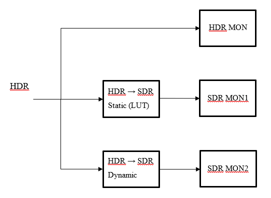
FIGURE A10-3 — Approach B – dynamic conversion applied for SDR monitoring (in comparison to static conversion)
图 A10-3. 方法 B——用于 SDR 监看的动态转换(与静态转换相比较)。
附件 11 — 203 cd/m² 与 100 cd/m²(BT.2035)SDR 信号格式之间的转换
Annex 11 — Conversion between 203 cd/m2 and 100 cd/m2 (BT.2035) SDR signal formats
Where SDR signals have been derived from an HDR production using the “203 cd/m2 single-stream HDR-SDR workflow” described in Annex 10, it may be desirable to convert them to the 100 cd/m2 SDR signal format for programme exchange.
当 SDR 信号是用附件 10 所述的“203 cd/m² 单流 HDR-SDR 工作流”从 HDR 制作导出时,可能需要把它们转换为 100 cd/m² 的 SDR 信号格式以供节目交换。
A similar method to that described in § 5.1.3.2 for direct-mapping of SDR into an HDR container can be used. But in this case, the intended displayed peak luminance is halved rather than doubled, and both input and output signals are SDR. The process is illustrated in Fig. A11-1.
可采用与 5.1.3.2 节所述把 SDR 直接映射进 HDR 容器相似的方法。但此处所期望的显示峰值亮度是减半而非加倍,且输入和输出信号都是 SDR。流程见图 A11-1。
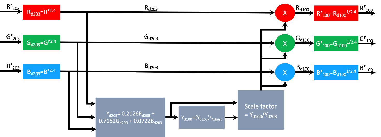
FIGURE A11-1 — Conversion of 203 cd/m2 SDR signals to 100 cd/m2 SDR signals
图 A11-1. 把 203 cd/m² SDR 信号转换为 100 cd/m² SDR 信号。
The nonlinear SDR R´G´B´ signal from the 203 cd/m2 SDR production is first converted to a normalised linear display light using a simple power law approximation to the BT.1886 EOTF. The resulting RGB signals were intended to be displayed at a nominal peak luminance of 203 cd/m2, denoted by the “d203” subscript, thus:
来自 203 cd/m² SDR 制作的非线性 SDR R′G′B′ 信号,先用 BT.1886 EOTF 的简单幂律近似转换为归一化的线性显示光。所得 RGB 信号本拟在 203 cd/m² 的标称峰值亮度下显示,以下标“d203”表示,于是:
The normalised linear luminance signal is calculated, in this case using the BT.709 R, G, B weighting factors:
随后计算归一化的线性亮度信号,本例使用 BT.709 的 R、G、B 加权系数:
The BT.2020 weighting factors are used for a BT.2020 SDR input. An appropriate signal luminance for display at a nominal peak luminance of 100 cd/m2, Y100, is then calculated. The 100 cd/m2 luminance signal is derived by first removing the OOTF (rendering intent) for a 203 cd/m2 display, to yield the scene-light signal YS, and then applying an appropriate OOTF (rendering intent) to YS for a 100 cd/m2 display. In a similar manner to the SDR to HDR direct-mapping described in § 5.1.3.2 the ratio of the rendering intents (OOTF gammas) may be determined by using the BT.2100 Note 5f (or Footnote 2) HDR gamma formula, to calculate the equivalent ratio of system gammas for HDR Reference White of the nominal 203 cd/m2 and 100 cd/m2.
对 BT.2020 SDR 输入则使用 BT.2020 加权系数。然后计算适合在 100 cd/m² 标称峰值亮度下显示的信号亮度 Y₁₀₀。100 cd/m² 亮度信号的导出方式是:先去除针对 203 cd/m² 显示设备的 OOTF(渲染意图),得到场景光信号 Y_S,再对 Y_S 施加针对 100 cd/m² 显示设备的合适 OOTF(渲染意图)。与 5.1.3.2 节所述 SDR 到 HDR 直接映射类似,两渲染意图之比(OOTF 伽马之比)可借助 BT.2100 注 5f(或脚注 2)的 HDR 伽马公式确定,以计算标称 203 cd/m² 与 100 cd/m² HDR 参考白所对应系统伽马的等效之比。
To obtain the 100 cd/m2 normalised RGB signals, a scale factor based on the ratio of the Yd100/Yd203 is applied to the linear Rd203, Gd203, Bd203 linear light signals, which is mathematically equivalent to preserving the chromaticity of the input signal but adjusting its luminance to match Yd100. The compensated non-linear R´100 G´100 B´100 signals for feeding a 100 cd/m2 display are then obtained by applying the inverse of the approximation of the BT.1886 EOTF.
为得到 100 cd/m² 的归一化 RGB 信号,把基于 Y_d100/Y_d203 之比的缩放因子施加到线性的 R_d203、G_d203、B_d203 线性光信号上——这在数学上等价于保持输入信号的色品、而把其亮度调整到与 Y_d100 相匹配。随后施加 BT.1886 EOTF 近似的逆运算,即可得到用于馈送 100 cd/m² 显示设备、经补偿的非线性 R′₁₀₀ G′₁₀₀ B′₁₀₀ 信号。
The following sections describe example use cases for conversion between 203 cd/m2 and 100 cd/m2 (BT.2035) SDR signal formats.
以下各节描述在 203 cd/m² 与 100 cd/m²(BT.2035)SDR 信号格式之间相互转换的示例用例。
A11.1 Example of optional gamma applied to SDR images
A11.1 对 SDR 图像施加可选伽马的示例
Philips performed an informal experiment to evaluate the appearance of an SDR signal that has been produced for a peak luminance of 203 cd/m2, when it is displayed instead on an SDR monitor with a peak luminance of 100 cd/m2, either directly or with an appropriate (gamma) correction.
飞利浦做了一项非正式实验,以评估为 203 cd/m² 峰值亮度制作的 SDR 信号,改在 100 cd/m² 峰值亮度的 SDR 监视器上显示(无论直接显示还是经适当的伽马校正)时的观感。
Without a correction, all luminances on the SDR monitor are downscaled by a factor 2.03 on the 100 cd/m2 peak luminance monitor, compared to the luminances shown during production on the 203 cd/m2 peak luminance monitor.
若不作校正,则与制作时在 203 cd/m² 峰值亮度监视器上所显示的亮度相比,100 cd/m² 峰值亮度监视器上的所有亮度都被缩小 2.03 倍。
According to this experiment, the linear downscaling of the luminances has the largest effect near black, making some detail near black invisible. To evaluate the visual impact, a gamma correction was applied to the signal with the goal of preserving the luminance of detail near black. The gamma correction value 1/1.08 was computed such that the luminances around an assumed perceivable black level of 0.02 cd/m2 are preserved between the 203 cd/m2 and 100 cd/m2 peak luminance monitors.
据该实验,亮度的线性缩小在接近黑处影响最大,使接近黑的一些细节不可见。为评估视觉影响,对信号施加了一道伽马校正,目的是保留接近黑的细节亮度。所算得的伽马校正值为 1/1.08,使在 203 cd/m² 与 100 cd/m² 峰值亮度监视器之间,假定可感知黑位 0.02 cd/m² 附近的亮度得以保留。
During the experiment, using original live HDR sports content, a visible difference in shadow detail near black could indeed be observed between the two SDR variants. But these visible differences were generally considered irrelevant, since they occurred, e.g. in shadow parts in corners and near the roof of the football stadium. However, differences could also be observed in parts of black clothing, in which case it could potentially be relevant to preserve the shadow detail on a 100 cd/m2 peak luminance monitor. Finally, there were no visible differences in the midtones and highlights between the two monitors.
实验中使用原始直播 HDR 体育内容,确实可在两种 SDR 变体之间观察到接近黑的暗部细节存在可见差异。但这些可见差异通常被认为无关紧要,因为它们出现在诸如球场角落和顶棚附近的阴影部分。不过,在黑色衣物的某些部位也能观察到差异,这种情况下在 100 cd/m² 峰值亮度监视器上保留暗部细节就可能有意义。最后,两台监视器之间在中间调和高光上没有可见差异。
Therefore, this informal subjective testing suggests that SDR live sports content produced at 203 cd/m2 peak luminance may be suitable for display on a 100 cd/m2 peak luminance reference monitor. Moreover, this testing found that an optional gamma 1/1.08 correction can be applied to the SDR signal to preserve shadow detail near black on a 100 cd/m2 peak luminance monitor, as shown in Fig. A11-2. In order to preserve the chromaticity, the gamma could be applied on the luminance, as described in this Annex, or on maxRGB (as described, e.g. in Annex 5).
因此,这项非正式主观测试表明,以 203 cd/m² 峰值亮度制作的 SDR 直播体育内容,可能适合在 100 cd/m² 峰值亮度的参考监视器上显示。此外,本测试发现,可对 SDR 信号施加一道可选的 1/1.08 伽马校正,以在 100 cd/m² 峰值亮度监视器上保留接近黑的暗部细节,如图 A11-2 所示。为保持色品,该伽马可施加于亮度(如本附件所述),也可施加于 maxRGB(如附件 5 所述)。
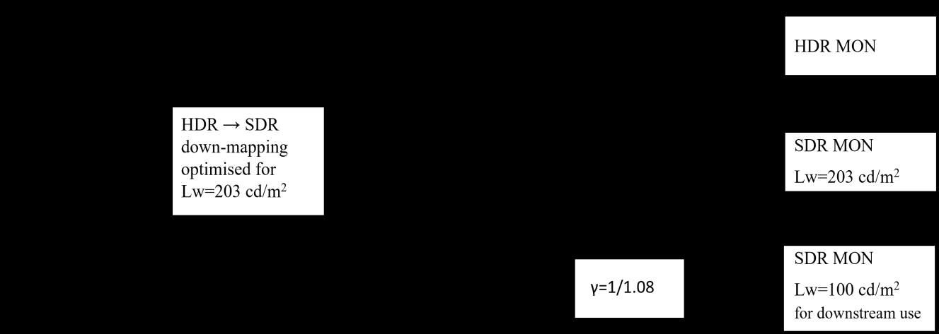
FIGURE A11-2 — Approach B - gamma correction applied for SDR images
图 A11-2. 方法 B——对 SDR 图像施加伽马校正。
A11.2 Example of optional gamma applied to SDR for monitoring
A11.2 对用于监看的 SDR 施加可选伽马的示例
An optional gamma correction can also be applied when an SDR signal intended for displaying on a monitor with a peak luminance of 100 cd/m2, should instead be monitored at a peak luminance of 203 cd/m2 (to enable SDR monitoring in close proximity to the HDR monitor). This could be useful, e.g. when the HDR to SDR conversion method/LUT was designed for SDR at a peak luminance of 100 cd/m2.
当本拟在 100 cd/m² 峰值亮度监视器上显示的 SDR 信号,需改在 203 cd/m² 峰值亮度下监看(以便与 HDR 监视器近距离并置监看 SDR)时,也可施加一道可选的伽马校正。这在 HDR 到 SDR 转换方法/LUT 是为 100 cd/m² 峰值亮度 SDR 设计的情形下可能有用。
Without a correction, all luminances on the SDR monitor are multiplied by a factor 2.03 on the 203 cd/m2 peak luminance monitor, compared to the luminances intended to be shown on the 100 cd/m2 peak luminance monitor.
若不作校正,则与本拟在 100 cd/m² 峰值亮度监视器上显示的亮度相比,203 cd/m² 峰值亮度监视器上的所有亮度都被乘以 2.03 倍。
According to the informal tests conducted by Phillips, the linear upscaling of the luminances has the largest effect near black, potentially making some detail or noise near black too visible. A gamma correction value of 1.08 has been computed using the method in § A.11.1 to preserve the luminances around an assumed perceivable black level of 0.02 cd/m2 between the 203 cd/m2 and 100 cd/m2 peak luminance monitors.
据飞利浦所做的非正式测试,亮度的线性放大在接近黑处影响最大,可能使接近黑的一些细节或噪声过于明显。用 A11.1 节的方法算得伽马校正值 1.08,以在 203 cd/m² 与 100 cd/m² 峰值亮度监视器之间,保留假定可感知黑位 0.02 cd/m² 附近的亮度。
This gamma can be applied as shown in Fig. A11-3. In order to preserve the chromaticity, the gamma could be applied on the luminance, as described in this Annex, or on maxRGB (as described, e.g. in Annex 5).
该伽马可按图 A11-3 所示施加。为保持色品,该伽马可施加于亮度(如本附件所述),也可施加于 maxRGB(如附件 5 所述)。
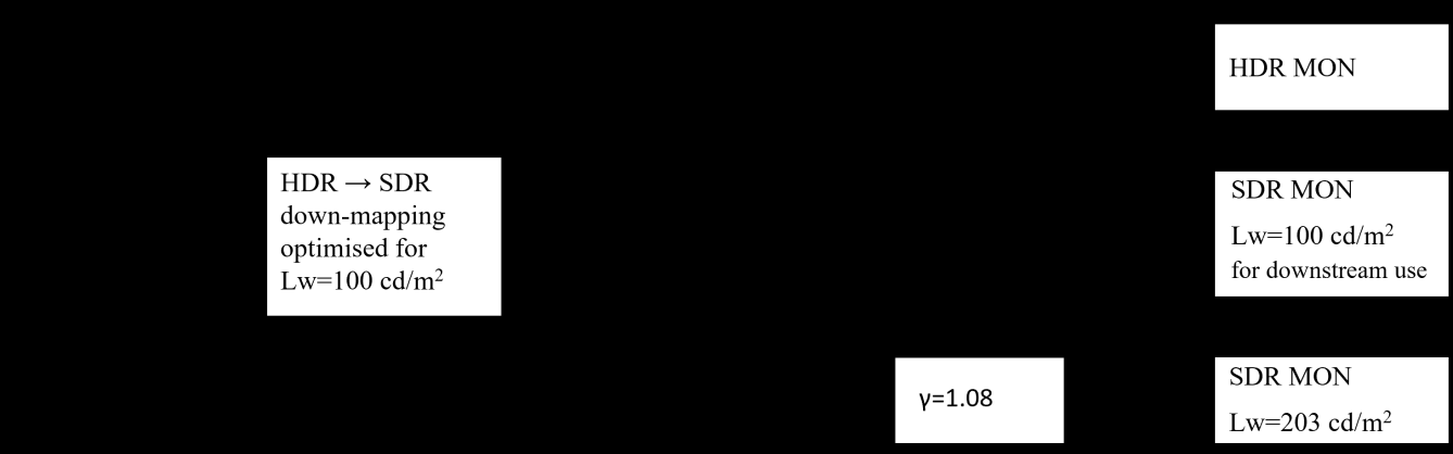
FIGURE A11-3 — Approach B - gamma correction applied for SDR monitoring
图 A11-3. 方法 B——对 SDR 监看施加伽马校正。
参考文献
[1] Fitzpatrick, T.B. (1988), “The validity and practicality of sun reactive skin types I through VI”. Arch Dermatol 124(6), pp. 869-871.
[2] K.C. Noland, M. Pindoria and A. Cotton, “Modelling brightness perception for high dynamic range television”, Ninth International Conference on Quality of Multimedia Experience (QoMEX), Erfurt, 2017.
[3] K.C. Noland and M. Pindoria, “A Brightness Measure for High Dynamic Range Television”, IBC Conference, September 2017.
[4] MovieLabs, “MovieLabs Best Practices for Mapping BT.709 Content to HDR10 for Consumer Distribution v1.0”, https://movielabs.com/download/938/.
[5] EBU Recommendation R103 version 3.0, “Video Signal Tolerance in Digital Television Systems”, May 2020 (https://tech.ebu.ch/docs/r/r103.pdf).
[6] K.C. Noland, “Optimal Interlacing using Human Sensitivity Measurements,” BBC R&D White Paper 315, May 2016.
[7] EBU TR 092, “Tests of Video Processing and Encoding for Contribution, v 1.1”, European Broadcasting Union, Geneva, Switzerland, October 2025 (https://tech.ebu.ch/publications/tr092).
[8] OpenEXR https://openexr.com/en/latest/
[9] Cooksey, C., Allen, D.W., et.al., “Reference Data Set of Human Skin Reflectance”, NIST Journal of Research, NIST, USA, Jun 2017.
[10] Jablonski N.G., Chaplin, G., “The evolution of human skin coloration”, Journal of Human Evolution, Vol. 39, 2000.
[11] ISO/CIE 11664-2:2022(en), “Colorimetry – Part 2: CIE Standard Illuminants”, International Organisation for Standardisation, Geneva 2022.
[12] Colour and Vision Research Laboratory, University College London, http://cvrl.ioo.ucl.ac.uk/.
[13] DCraw https://www.cybercom.net/~dcoffin/dcraw/.
[14] Australian Radiation Protection and Nuclear Safety Agency, “Fitzpatrick Skin Type”, questionnaire to determine Fitzpatrick Skin Type https://www.arpansa.gov.au/sites/g/files/net3086/f/legacy/pubs/RadiationProtection/FitzpatrickSkinType.pdf.
[15] Burk, A., Smith, M., Zink, M., “Color Volume and Hue-Preservation in HDR Tone Mapping”, SMPTE Motion Imaging Journal. May 2020.
[16] SMPTE ST 303:2002, “Color reference pattern”.
[17] ISO/CIE 11664-5:2024, “Colorimetry – Part 5: CIE 1976 Luv* colour space and u’, v’ uniform chromaticity scale diagram”.
[18] Elena A. Fedorovskaya and Huib de Ridder, “Subjective matters: from image quality to image psychology”, Proc. SPIE 8651, Human Vision and Electronic Imaging XVIII, 86510O (23 March 2013); https://doi.org/10.1117/12.2008681
[19] ISO/CIE 11664-6:2022, “Colorimetry – Part 6: CIEDE2000 Colour-difference formula”.
[20] NBCU UHD-HDR-SDR “Single-Master” Production Workflow Recommendation & LUTS for Public Distribution, https://github.com/digitaltvguy/NBCUniversal-UHD-HDR-SDR-Single-Master-Production-Workflow-Recommendation-LUTs.
[21] “High-Performance Single Layer High Dynamic Range (HDR) System for use in Consumer Electronics devices; Part 1: Directly Standard Dynamic Range (SDR) Compatible HDR System (SL-HDR1)”, ETSI TS 103 433-1 V1.4.1, August 23, 2021.
[22] D. Touze et al., “HDR Production – Tone Mapping Techniques and Roundtrip Conversion Performance for Mastering With SDR and HDR Sources,” in SMPTE Motion Imaging Journal, vol. 132, no. 6, pp. 31-44, July 2023, doi: 10.5594/JMI.2023.3277092.
[23] B. Redmann et al., “HDR Challenges and Solutions,” in SMPTE Motion Imaging Journal, vol. 132, no. 10, pp. 27-42, Nov.-Dec. 2023, doi: 10.5594/JMI.2023.3325513.
术语表
Following is a list of terms within Report ITU-R BT.2408 which may not have been encountered by the reader in the context of High Dynamic Range.
以下列出报告 ITU-R BT.2408 中读者在高动态范围背景下可能不太熟悉的若干术语。
Camera painting – the process of adjusting the image within the camera or external processor, to balance the colours and tones to create a desired aesthetic.
摄像机调校(painting)——在相机内或外部处理器中调整图像、平衡色彩和色调以营造所需美学的过程。
Camera RAW signals – image data produced by, or internal to, a digital camera that has not been processed, except for A/D conversion and the following optional steps: linearization, dark current/frame subtraction, shading and sensitivity (flat field) correction, flare removal, white balancing (e.g. so the adopted white produces equal RGB values or no chrominance), missing colour pixel reconstruction (without colour transformations).
相机 RAW 信号——由数字相机产生或在其内部生成、未经处理的图像数据,但以下步骤除外:模数(A/D)转换,以及如下若干可选步骤——线性化、暗电流/暗场扣除、阴影与灵敏度(平场)校正、去除杂散光、白平衡(如使所采用的白产生相等的 RGB 值或不含色度信息)、缺失颜色像素的重建(不含色彩变换)。
Camera shading – a chain of operational camera adjustments required to match cameras in live (or as-live) production to give and maintain the desired look by means of, for example, camera presets, black level adjustment, iris/exposure, painting controls, colour balance and real-time signal level adjustment.
摄像机明暗控制(shading)——为在直播(或准直播)制作中匹配各相机、赋予并维持所需观感而进行的一连串操作性相机调整,手段包括相机预设、黑位调整、光圈/曝光、调校控制、色彩平衡和实时信号电平调整等。
Colour branding – the intentionally applied look of graphics added to a programme designed to create or maintain a consistent and familiar appearance.
品牌配色——为节目所添加图形有意施加的观感,旨在创造或维持一致而为人熟悉的外观。
Colour correction – the process of adjusting a series of clips in post-production, so that they have a consistent appearance aligned with the production.
校色——在后期对一系列片段进行调整,使其外观一致并与整部制作相协调的过程。
Colour grading – the process of further adjusting the image in post-production, to balance the colours and tones to create the desired aesthetic. Colour grading is usually performed after colour correction.
调色——在后期进一步调整图像、平衡色彩和色调以营造所需美学的过程。调色通常在校色之后进行。
Display light – image values that result from applying the reference EOTF to the encoded image signal values.
显示光——对已编码图像信号值施加参考 EOTF 所得到的图像值。
Display-light conversion – conversion of image data performed by converting the image data to display light using the reference EOTF of the first encoding, and then applying the reference inverse EOTF for the second encoding, typically used for preserving the appearance of graded content.
显示光转换——一种图像数据转换:先用第一种编码的参考 EOTF 把图像数据转换为显示光,再施加第二种编码的参考逆 EOTF;通常用于保留已调色内容的观感。
Dual-focused monitoring - a monitoring technique where monitors placed in close proximity are used to simultaneously compare HDR and SDR images.
双重心监看——一种监看技术,把近距离并置的监视器用于同时比较 HDR 与 SDR 图像。
Dual-focused workflow – all critical video adjustments are made by viewing images simultaneously on HDR and SDR monitors placed in close proximity.
双重心工作流——所有关键的视频调整,都通过在近距离并置的 HDR 与 SDR 监视器上同时观看图像来完成。
Eye adaptation – the autonomic (involuntary) adjustment of the eye to different light levels.
眼睛适应——眼睛对不同光照水平的自主(不自觉)调节。
Gregory hole reference – an object used as reference black with 0% reflectance, typically a box lined with black material designed to absorb light and prevent reflections of light which is viewed through a small opening.
格雷戈里孔参考体——一种用作参考黑、反射率为 0% 的物体,通常是一个内衬黑色材料、用于吸收光并防止反射的盒子,从一个小开口观察。
HDR-focused workflow – all critical video adjustments are made by viewing images on an HDR monitor.
以 HDR 为重心的工作流——所有关键的视频调整都通过在 HDR 监视器上观看图像来完成。
HDR reference white – the nominal signal level obtained from an HDR camera and a 100% reflectance white card resulting in a nominal luminance of 203 cd/m2 on a PQ display or on an HLG display that has a nominal peak luminance capability of 1 000 cd/m2.
HDR 参考白——用 HDR 相机对着一张 100% 反射率白卡所得到的标称信号电平,它在 PQ 显示设备上、或在标称峰值亮度能力为 1 000 cd/m² 的 HLG 显示设备上,对应 203 cd/m² 的标称亮度。
Lambertian reflector – a reflecting surface which reflects incident light in all directions, giving the same apparent brightness regardless of the angle of view of an observer.
朗伯反射体——一种把入射光向各个方向反射的反射表面,无论观察者的视角如何,其表观明亮度都相同。
Luma – a term specifying that a signal represents the monochrome information related to non-linear colour signals. The symbol for luma information is denoted as Y′.
NOTE – The term luma is used rather than the term luminance in order to signify the use of non-linear light transfer characteristics as opposed to the linear characteristics in the term luminance. However, in many of the ITU-R Recommendations on television systems, the term “luminance signal” is used rather than “luma” for Y′ together with C′B and C′R.
亮度信号(Luma)——表示信号代表与非线性颜色信号相关的单色信息。亮度信号信息的符号记为 Y′。
注——之所以用 luma 而非 luminance(亮度),是为了表明采用的是非线性光传输特性,以区别于 luminance 所含的线性特性。不过,在许多关于电视系统的 ITU-R 建议书中,与 C′B、C′R 并列的 Y′ 用的是“亮度信号(luminance signal)”一词,而非“luma”。
Luminance – the photometrically weighted flow of light per unit area travelling in a given direction. It describes the amount of light that passes through, is emitted from, or is reflected from a particular area, and falls within a given solid angle. It is expressed in candelas per square meter (cd/m2).
NOTE – The relative luminance of a pixel can be approximated by a weighted sum of the linear colour components; the weights depend on the colour primaries and the white point.
亮度(Luminance)——沿给定方向、经光度学加权的单位面积光通量。它描述通过、发自或反射自某一特定面积、并落入给定立体角内的光量,以坎德拉每平方米(cd/m²)表示。
注——一个像素的相对亮度可用各线性颜色分量的加权和来近似,权重取决于基色和白点。
Scene light – image values that result from applying the inverse reference OETF to the encoded image signal values.
场景光——对已编码图像信号值施加参考 OETF 的逆所得到的图像值。
Scene-light conversion – conversion of image data performed by converting the image data back to scene light using the inverse of the first encoding reference OETF, and then applying the reference OETF for the second encoding, typically used for matching cameras.
NOTE – The image data can be from a graded source (for example, from a camera that has been adjusted to give a particular desired appearance on a reference monitor), but scene light conversions might not preserve the colour appearance produced on the reference monitor.
场景光转换——一种图像数据转换:先用第一种编码参考 OETF 的逆把图像数据转换回场景光,再施加第二种编码的参考 OETF;通常用于匹配相机。
注——图像数据可来自已调色的源(例如来自经调整、以在参考监视器上呈现某种所需观感的相机),但场景光转换未必能保留在参考监视器上所产生的色彩观感。
Overshoots – signal excursions above nominal peak level.
过冲——信号摆动到标称峰值电平之上。
SDR-focused workflow – all critical video adjustments are made by viewing images on an SDR monitor where the image has been down-mapped from an HDR signal.
以 SDR 为重心的工作流——所有关键的视频调整,都通过在 SDR 监视器上观看由 HDR 信号下映射而来的图像来完成。
Single-master HDR production – a production approach that uses a single (master) HDR video format within the vision mixer (video switcher). The output of a ‘Single-master HDR production’ simultaneously includes a down-mapped SDR output in addition to the native HDR output.
单母版 HDR 制作——一种在视频切换台内使用单一(母版)HDR 视频格式的制作方式。“单母版 HDR 制作”的输出,除原生 HDR 输出外,还同时包含一路下映射所得的 SDR 输出。
Sub-blacks – in a narrow range signal, a video signal of lower than 0% black level extending down to approximately 6.8% below black level. In the case of 10-bit digital coding this range lies below value 64 (black level) extending down to value 4, while in 12-bit digital coding this range lies below value 256 extending down to value 17.
次黑(sub-black)——在窄范围信号中,指低于 0% 黑位、向下延伸至黑位以下约 6.8% 的视频信号。在 10 比特数字编码中,这一范围位于 64(黑位)之下、向下直至 4;在 12 比特数字编码中,则位于 256 之下、向下直至 17。
Super-white – in a narrow range signal, a video signal of greater than 100% nominal peak level extending up to 109% of nominal peak level. In the case of 10-bit digital coding this range lies above value 940 (nominal peak) extending to value 1 019, while in 12-bit digital coding this range lies above value 3 760 extending to value 4 079.
超白——在窄范围信号中,指超过标称峰值电平 100%、最高可达标称峰值电平 109% 的视频信号。在 10 比特数字编码中,这一范围位于 940(标称峰值)之上、直至 1 019;在 12 比特数字编码中,则位于 3 760 之上、直至 4 079。
Undershoots – signal excursions below black level.
下冲——信号摆动到黑位之下。
Vision engineer – also known as a vision shader. Vision engineers are responsible for camera shading.
视频工程师——又称视频控制员(vision shader)。视频工程师负责摄像机明暗控制。
Vision supervisor – determines the overall look of the production in conjunction with the production team. The vision supervisor coordinates global adjustments of cameras with vision engineers (shaders) and where applicable, lighting supervisors.
视频主管——与制作团队一同确定整部制作的整体观感。视频主管与视频工程师(视频控制员)、以及在适用时与灯光主管,协调对各相机的全局调整。
- 1.漫反射白是由一张近似完美反射漫射体的卡所提供的白:它在光谱上为灰(而不仅是在色度上为灰),尽量减少镜面高光,并尽量减少光谱功率吸收。“完美反射漫射体”定义为“理想的各向同性、非荧光漫射体,在每个所关注波长上的光谱辐亮度因数均等于 1”。 ↩
- 2.测试图卡应由前置灯照明,相机应从非镜面方向拍摄图卡。 ↩
- 3.“亮度因数”是某表面元在给定方向上的亮度,与在相同照明下完美反射或透射漫射体的亮度之比。 ↩
- 4.第 1 型、第 5 型和第 6 型肤型的实验数据有限,因此这些肤型的信号范围确定性较低。 ↩
- 5.这可以包括在一台带 UHD HDR 传感器、正生成 HD HDR 输出的相机内部进行的转换。 ↩
- 6.在本附件中,漫反射白元素的电平简称为“漫反射白”。 ↩
- 7.CMG:中央广播电视总台(China Media Group)——下辖 CCTV、CNR、CRI、CGTN。 ↩
转载请注明来源。欢迎留言评论,欢迎对文章中的引用来源进行考证,欢迎指出任何有错误或不够清晰的表达。