原文:Report ITU-R BT.2390-12 (03/2025) — High dynamic range television for production and international programme exchange
报告:ITU-R BT.2390-12(2025 年 3 月)
BT 系列:广播业务(电视)
作者:国际电信联盟无线电通信局(ITU-R)
版本沿革:02/2016-10/2016-03/2017-10/2017-04/2018-10/2018-04/2019-07/2019-2020-03/2021-11/2021-2023-2025
翻译:Horace Lu
摘要
Recommendation ITU-R BT.2100 – Image parameter values for high dynamic range television for use in production and international programme exchange, specifies parameters for High Dynamic Range television (HDR-TV) signals to be used for programme production and international programme exchange. This Report provides background information on HDR in general, and for the perceptual quantization (PQ) and hybrid log-gamma (HLG) HDR signal parameters specified in the Recommendation.
建议书 ITU-R BT.2100《用于制作与国际节目交换的高动态范围电视的图像参数值》规定了用于节目制作与国际节目交换的高动态范围电视(HDR-TV)信号参数。本报告介绍 HDR 的总体背景,并对该建议书所规定的感知量化(PQ)和混合对数伽马(HLG)两类 HDR 信号参数加以说明。
目录
- 摘要
- 目录
- 1 HDR 电视的简介与设计目标
- 2 电视系统架构
- 3 传统电视架构
- 4 RGB 浮点 HDR-TV 系统
- 5 PQ HDR-TV
- 6 HLG HDR-TV
- 7 用于色度子采样的色彩表示
- 参考文献
- 术语表
1 Introduction and design goals for HDR television
1 HDR 电视的简介与设计目标
HDR-TV enables more natural images that contain wider variations in brightness. While HDR-TV does allow the picture average brightness to increase, the expectation is that indoor scenes produced in HDR will generally be at a similar brightness as with legacy TV systems. The brightness range available with HDR enables outdoor sunlit scenes to appear noticeably brighter than indoor scenes, thus providing a more natural look. All scenes, especially outdoor, will be able to produce small area highlights such as specular reflections or emissive light sources at much higher brightness. There is also an improvement in the ability to show details in dark areas; this feature is dependent on the black level of the display and the viewing environment.
HDR-TV 能呈现亮度变化范围更宽、更自然的图像。HDR-TV 确实允许画面平均亮度提高,但通常预期是:用 HDR 制作的室内场景,亮度大体上与传统电视系统相当。HDR 提供的亮度范围让阳光下的室外场景明显比室内场景更亮,画面因而更显自然。所有场景,尤其是室外场景,都能以高得多的亮度呈现镜面反射、自发光光源之类的小面积高光。HDR 在暗部细节的表现力上也有提升,这一点取决于显示设备的黑位和观看环境。
1.1 Common misconceptions on HDR
1.1 关于 HDR 的常见误解
HDR for video and display is an entire ecosystem that encompasses much more than the words underlying the acronym. Before discussing system issues, there are number of frequent misconceptions about HDR video, such as: ‘It is all about brighter pictures’, ‘It is all about dynamic range’, ‘It is all about bit-depth’, ‘It is primarily an image capture issue’, ‘It is primarily a display capability issue’, ‘It makes images look like paintings’.
视频与显示领域的 HDR 是一整套生态系统,远不止其英文缩写字面所指的那点含义。在讨论系统问题之前,先澄清几个关于 HDR 视频的常见误解,例如:“无非就是画面更亮”“无非就是动态范围”“无非就是位深”“主要是图像采集的问题”“主要是显示能力的问题”“它会把图像弄得像油画”。
Of these, only the first one here will be addressed. The misconception about HDR being simply brighter1 pictures arises from the fact that the maximum luminance capability is indeed much higher than standard dynamic range (SDR) television. However, this higher maximum is primarily used by the highlight regions of images. While the highlights will indeed appear brighter [1], they are nearly always small in region, and the overall image may not necessarily appear brighter. This is because the overall appearance of an image’s brightness is dominated by the average brightness, not the small regions usually occupied by highlights. One type of highlight is the specular reflection. The advantages of having more accurate specular reflections enabled by HDR include better surface material identification [2] as well as in depth perception, even with 2D imagery [3] [4].
这里只澄清第一个。认为 HDR 不过是让画面更亮[1],这种误解源于:HDR 的最大亮度能力确实远高于标准动态范围(SDR)电视。然而,这一更高的峰值主要供图像的高光区域使用。高光确实会显得更亮 [1],但它们几乎总是只占很小的区域,整幅图像未必看上去更亮。原因在于:一幅图像的整体明亮程度由平均亮度决定,而非由高光通常占据的那些小区域决定。镜面反射就是高光的一种。HDR 能更准确地还原镜面反射,由此带来的好处包括:更便于识别表面材质 [2],即便是二维图像也能改善深度感知 [3] [4]。
By comparison, in the process of making the SDR content (whether colour grading in post-production or selection of the camera settings in live broadcast), human decisions are invariably made to fit the higher dynamic range of the scenes into the standard range.
相比之下,制作 SDR 内容时(无论是后期的调色,还是直播中相机参数的选择),总要靠人为决策,把场景较高的动态范围塞进标准范围里。
In typical practice, highlights are processed through a shoulder operation or simply clipped. This loses not only the amplitudes of the highlights, but also the details within and around the highlights. Similarly, shadow detail is lost. Colour emissive highlights result in the colour component going through different portions of the shoulders such that the colour shifts towards white. These different aspects resulted in the realization that a new HDR signal format needed to be developed to allow for the HDR display to truly deliver an HDR experience.
通常的做法是用肩部操作来处理高光,或干脆将其削掉。这样不仅丢失了高光的幅度,也丢失了高光内部及周围的细节。暗部细节同样会丢失。彩色自发光高光还会使各颜色分量分别落在肩部曲线的不同段上,导致色彩偏向白色。正是这些问题让人们认识到:必须开发一种新的 HDR 信号格式,HDR 显示设备才能真正带来 HDR 体验。
There is another way to utilize the new range capabilities than to utilize it solely for highlights. This is to allow for more realistic scene-to-scene luminance variations. In current SDR, with a range of less than three log10 luminance, it was always difficult to render evening scenes, and nearly impossible to render the luminance differences of indoor and outdoor scenes. Acknowledging this limitation with SDR, some creatives like to use the increased dynamic range of HDR to have larger scene-to-scene variations in mean luminance. So, for this particular approach, HDR may result in brighter images for some scenes.
除了把新增的范围能力专用于高光之外,还有另一种用法:让场景与场景之间的亮度变化更逼真。当前 SDR 的亮度范围不足 3 个数量级(log₁₀),一向难以表现傍晚场景,几乎不可能表现室内与室外场景之间的亮度差异。意识到 SDR 的这一局限后,一些创作者乐于利用 HDR 更大的动态范围,让各场景的平均亮度之间有更大的起伏。因此,就这种用法而言,HDR 确实可能让某些场景的图像更亮。
However, despite these variations in intent for invoking increased brightness, HDR also allows for lower black levels than traditional SDR, which was typically in the range between 0.1 and 1.0 cd/m2 for cathode ray tubes (CRTs) and is now in the range of 0.1 cd/m2 for most standard SDR liquid crystal displays (LCDs). So, a key design question is how low should the black level be.
不过,尽管提升亮度的意图各不相同,HDR 同时也允许比传统 SDR 更低的黑位。传统 SDR 的黑位,阴极射线管(CRT)一般在 0.1 至 1.0 cd/m² 之间,如今大多数标准 SDR 液晶显示器(LCD)则在 0.1 cd/m² 上下。于是,一个关键的设计问题是:黑位究竟应该有多低。
1.2 System black level determination
1.2 系统黑位的确定
In order to determine the system black level, the state of light adaptation2 is central. The classic psychophysical study on dark adaptation was by Hecht et al [5], which corresponds to the top data line of the plot in Fig. 1, which is a compilation of more recent studies [6]. The left branch of the curve corresponds to the cones, while the right branch of the curve corresponds to rod vision. While threshold values of less than 0.00001 cd/m2 can be obtained, they can take significant durations of dark adaptation, which are not likely in entertainment media. If one restricts consideration to cone vision’s left branch of the uppermost curve, visibility does not go as low, but it still can be below ~0.02 cd/m2.
确定系统黑位时,光适应[2]状态是核心因素。关于暗适应的经典心理物理学研究出自 Hecht 等人 [5],对应图 1 中最上方的一条数据线;图 1 汇集了较新的研究成果 [6]。曲线的左支对应视锥细胞,右支对应视杆视觉。虽然可以测得低于 0.00001 cd/m² 的阈值,但那需要相当长的暗适应时间,在娱乐媒体中不大可能出现。若只考虑最上方曲线左支所代表的视锥视觉,可见的下限没有那么低,但仍可低至约 0.02 cd/m² 以下。
However, detectability as low as 0.02 cd/m2 seems to require minutes of dark adaptation time, which in traditional entertainment media is considered unrealistic3. Often, the early part of the curve (< 1 minute) is used to conclude that black levels of between 0.3 and 1.0 cd/m2 are sufficient, and in previous years display capability has been limited to be greater than 0.1 cd/m2 (e.g. for fixed backlight LCD). Using data such as those presented in Fig. 1 to conclude that the human eye cannot see black level differences below 0.1 cd/m2 overlooks that the curves depend on the initial adaptation condition. The other curves shown in the figure show that as the initial adaptation level is lowered, the ability to see lower luminance levels improves. While the plotted time scale does not allow for determination of adaptation ranges on the order of video scene cuts (3-5 s), the leftmost data points are enough to show that visual detectability of black level can be close to 0.001 cd/m2 for the 25 cd/m2 initial level, close to SDR average luminance levels (i.e. average picture level (APL)). Thus from Fig. 1, one would easily conclude that the black level of video should allow levels as low as 0.001 cd/m2.
不过,要分辨低至 0.02 cd/m² 的黑位,似乎得有几分钟的暗适应时间,这在传统娱乐媒体中被认为不切实际[3]。人们常用曲线的早段(不足 1 分钟)来推断:0.3 至 1.0 cd/m² 的黑位已经够用;过去几年里,显示设备的能力也被限制在 0.1 cd/m² 以上(如固定背光的 LCD)。但若据图 1 这类数据就断言人眼看不出 0.1 cd/m² 以下的黑位差异,那就忽略了一点:这些曲线取决于初始适应条件。图中其余曲线表明,初始适应亮度越低,看清更低亮度的能力越强。图中的时间尺度虽不足以测定视频镜头切换那种量级(3—5 秒)的适应范围,但最左侧的数据点已足以说明:当初始亮度为 25 cd/m²(接近 SDR 的平均亮度,即平均图像电平 APL)时,黑位的视觉可分辨下限可接近 0.001 cd/m²。因此,从图 1 不难得出结论:视频的黑位应允许低至 0.001 cd/m²。
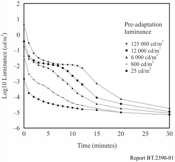
FIGURE 1 — Black level detectability as a function of duration for different initial adaptation levels. From Stokkerman [6]
图 1. 不同初始适应亮度下,黑位可分辨性随时间的变化。摘自 Stokkerman [6]
However, system design by the use of data as in Fig. 1 leans toward the most demanding cases, where the entire image may be dark. Other approaches consider that images generally do not consist of all-dark regions; there is a mixture of different luminance levels. The general approach is to treat the image as a surround around a possible black area. Using rectangular patches with a white surround, Mantiuk et al [7] studied black level threshold as a function of the size of the black region. The area outside of the patch was termed the surround, and the surround serves as a surrogate for an actual image with average image luminance level. The results in Fig. 2 show the lowest black level that can be discriminated from zero luminance is ~−2.4 log10 cd/m2 (0.0039 cd/m2), at least for the darkest surround that they studied, which was 0.1 cd/m2. Lower thresholds would be expected from darker surrounds, such as might occur in home theatre, or some evening viewing situations.
不过,依图 1 这类数据来做系统设计,偏向了最苛刻的情形——整幅图像可能都很暗。另一些思路则认为,图像一般不会全是暗区,而是各种亮度电平的混合。常见做法是把图像看作环绕在某块黑区周围的周边。Mantiuk 等人 [7] 以白色周边包围矩形色块,研究了黑位阈值随黑区面积的变化。色块以外的区域称为周边,它充当一幅具有平均图像亮度的真实图像的替身。图 2 的结果显示,至少对他们所研究的最暗周边(0.1 cd/m²)而言,能与零亮度区分开的最低黑位约为 −2.4 log₁₀ cd/m²(即 0.0039 cd/m²)。周边更暗时(如家庭影院或某些傍晚观看场景),阈值预计还会更低。
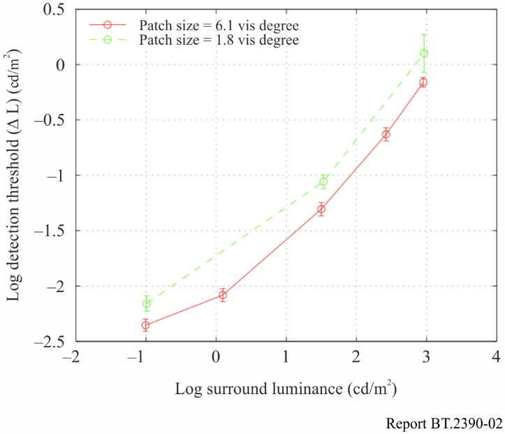
FIGURE 2 — Detectability of black level differences for a rectangular patch of either 6.1 or 1.8 visual degrees, both as a function of surround luminance level
图 2. 视角分别为 6.1° 与 1.8° 的矩形色块,其黑位差异可分辨性随周边亮度的变化。
Two things are clear. As the surround luminance decreases, the detectable black level decreases. That is, the expected surround luminance that results from practical imagery can determine the necessary black level to achieve a pure black perception, as well as finding the level where dark detail is no longer distinguishable. The other effect is that thresholds for the larger black region are lower than for the smaller. Thus in designing a system black level, the expected size of the black region is a key factor. Note that the largest region studied in this work was 6 degrees, whereas the image size for HDTV viewed at 3H is approximately 35 degrees (UHDTV @ 1.5 H is ~70 degrees).
有两点很清楚。其一,周边亮度越低,可分辨的黑位越低。也就是说,实际图像所产生的周边亮度,既能决定要获得纯黑感知所需的黑位,也能确定暗部细节不再可辨的电平。其二,较大黑区的阈值低于较小黑区。因此,设计系统黑位时,黑区的预期面积是一个关键因素。需要注意,本研究考察的最大黑区为 6°,而 HDTV 在 3 倍画面高度(3H)距离观看时的图像视角约为 35°(UHDTV 在 1.5H 处约为 70°)。
Another approach for determining system black level is to not base it on psychophysical detection tasks with abstract geometric stimuli, but rather use preferences while viewing more natural imagery. Rempel at al. [8] measured preference for display black level and brightness in short video clips (a sitcom) and found all participants consistently set the black level to the lowest possible setting, which was about 0.3 cd/m2 for their display. So, the only conclusion from this was that 0.3 is not low enough. A more recent study using an experimental HDR display with very low black level capability [9] [10] [11] found levels near its minimum capability, which was 0.004 cd/m2. In order to meet the preferences of 90% of the viewers, a level of 0.005 cd/m2 was needed. The typical current black level LCD TVs of 0.1 cd/m2 would meet the preferences of only half of the viewers. Results are shown in Fig. 3.
确定系统黑位的另一种思路,不依据用抽象几何刺激做的心理物理探测任务,而是依据观看更自然图像时的偏好。Rempel 等人 [8] 用短视频片段(一部情景喜剧)测量了观众对显示黑位和亮度的偏好,发现所有受试者都一致把黑位调到尽可能低的设置,对他们所用的显示设备而言约为 0.3 cd/m²。由此只能得出一个结论:0.3 还不够低。一项较新的研究 [9] [10] [11] 使用了一台黑位能力极低的实验性 HDR 显示设备,测得的偏好电平接近其最低能力,即 0.004 cd/m²。要满足 90% 观众的偏好,需要 0.005 cd/m² 的电平。而当前典型 LCD 电视 0.1 cd/m² 的黑位,只能满足一半观众的偏好。结果见图 3。
The plot in Fig. 3 demonstrates the results of psychophysical experiments designed to understand the preferred dynamic range [9] [10] [11]. The experiment was based on a two-alternative forced choice paradigm using static images shown sequentially for average shot durations (2 to 5 s) and trial durations of around 20 s to include response times, for an experiment lasting a total of 40 minutes per participant. The stimuli were drawn from three classes of images, containing shadow detail, reflective white stimuli, and highlight stimuli. A dual modulation display was used using an LCD panel backlit by a digital cinema projector, allowing a luminance range between 0.004 and 20 000 cd/m2. Separate experimental sessions were conducted for the black level scenes vs. the white and highlight level scenes; the results of all the experiments are plotted on the same Figure but this should not be interpreted as indication that both extremes can be perceived simultaneously.
图 3 展示的是一组旨在了解观众偏好动态范围的心理物理实验结果 [9] [10] [11]。实验采用二选一强迫选择范式,依次呈现静态图像,每幅按平均镜头时长(2—5 秒)显示,单次试验时长约 20 秒以涵盖反应时间,每位受试者总计实验约 40 分钟。刺激取自三类图像,分别含暗部细节、反射白刺激和高光刺激。所用显示设备为双调制显示,由数字电影放映机背光照射 LCD 面板,亮度范围在 0.004 至 20 000 cd/m² 之间。黑位场景与白位、高光场景分别在不同的实验环节进行;所有实验结果绘于同一张图上,但这并不意味着两个极端能被同时感知。
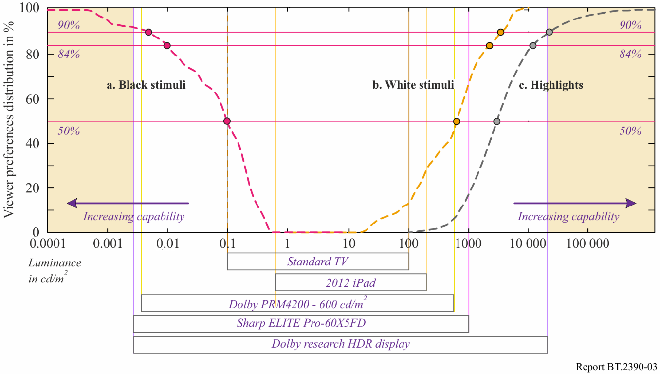
FIGURE 3 — Cumulative distribution functions for a. black stimuli, b. reflective white stimuli and c. emissive and highlights. For comparison, the dynamic ranges of common displays are given
图 3. 累积分布函数:a. 黑色刺激,b. 反射白刺激,c. 自发光与高光刺激。图中并列给出常见显示设备的动态范围以资比较。
Regarding the black level, there are a number of studies that found detectability as well as preferences well below the level of 0.1 cd/m2, which was common for SDR displays. Values in the range of 0.001 to 0.005 cd/m2 could be deduced from the studies described here, and regarding preferences there may be upward biases due to the smaller field of view used in [9] than occurs with UHDTV.
就黑位而言,多项研究发现,无论是可分辨性还是偏好,都远低于 SDR 显示设备常见的 0.1 cd/m²。由上述研究可推断出 0.001 至 0.005 cd/m² 的取值范围;至于偏好值,由于文献 [9] 所用视场比 UHDTV 实际视场更小,可能存在偏高的倾向。
1.3 System white and highlight level determination
1.3 系统白位与高光电平的确定
In video, the system white is often referred to as reference white, and is neither the maximum white level of the signal nor that of the display. When calibration cards are used to set the reference white, it is a diffuse white (also called matte) that is placed on the card, and measured. The ideal diffuse white has a Lambertian reflection. The luminances that are higher than reference white are referred to as highlights. While there are several key quality dimensions and creative opportunities opened up by HDR (e.g. shadow detail, handling indoor and outdoor scenes simultaneously, and colour volume aspects), one of the key differentiators from SDR is the ability for more accurate rendering of highlights. These can be categorized as two major scene components: specular reflections4 and emissives (also referred to as self-luminous). They are best considered relative to the maximum diffuse white luminance in the typical image. Most scenes can be broken down into two key ranges: object’s diffuse reflectances and the highlights. (Some scenes would defy such categorization, e.g. fireworks at night.) The object’s reflectance is important to convey its shape due to shading and other features, and the visual system has strong ability to discount the illuminant to be able to estimate the reflectance [12].
在视频中,系统白常被称为参考白,它既不是信号的最大白电平,也不是显示设备的最大白电平。用校准卡设定参考白时,置于卡上并加以测量的是漫反射白(也称无光泽白)。理想的漫反射白具有朗伯反射特性。高于参考白的亮度称为高光。HDR 开启了若干关键的画质维度和创作可能(如暗部细节、同时处理室内外场景、色彩体积等),而它区别于 SDR 的关键之一,是能更准确地还原高光。高光可归为两大类场景成分:镜面反射[4]和自发光(也称自照明)。考量它们时,最好以典型图像中漫反射白的最大亮度为参照。大多数场景可分解为两个关键范围:物体的漫反射率和高光。(有些场景无法这样归类,如夜空中的烟花。)物体的反射率借由明暗和其他特征来传达其形状,因此十分重要;而视觉系统具有很强的能力,能够剔除光源的影响来估计反射率 [12]。
However, the human ability to perceive both types of highlights is much less accurate and less computationally sophisticated as the ability perceive reflectances [12]. Illustrations of emissives and specular highlights are shown in Fig. 4.
然而,人类感知这两类高光的能力,远不如感知反射率那样精确,所涉及的运算也没那么复杂 [12]。自发光与镜面高光的示例见图 4。
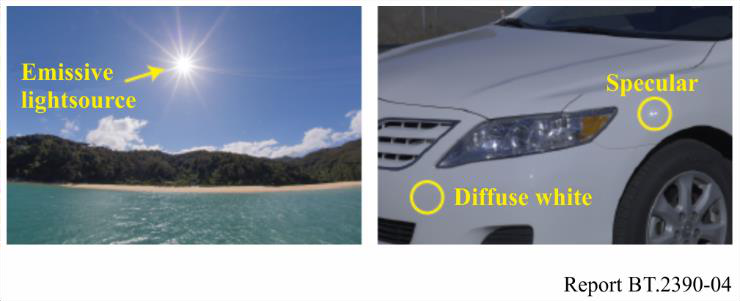
FIGURE 4 — Emissive light sources, specular reflections, and diffuse white
图 4. 自发光光源、镜面反射与漫反射白。
In traditional imaging, the range allocated to these highlights was fairly low and the majority of the image range was allocated to the diffuse reflective regions of objects. For example, in hardcopy print the highlights would be 1.1x higher luminance than the diffuse white maximum. In traditional video, the highlights were generally set to be no higher than 1.25x the diffuse white. Of the various display applications, cinema allocated the highest range to the highlights, up to 2.7x the diffuse white.
在传统成像中,分配给高光的范围相当有限,图像范围的大部分都留给了物体的漫反射区。例如,纸质打印中高光的亮度比漫反射白的最大值高出约 1.1 倍;传统视频中高光一般设定为不超过漫反射白的 1.25 倍。在各类显示应用里,电影分配给高光的范围最大,可达漫反射白的 2.7 倍。
Actual measurements show the specular regions can be over 1 000x higher than the underlying diffuse surface [2], which is presented in Fig. 5. This means the physical dynamic range of the specular reflections vastly exceed the range occupied by diffuse reflection. If a visual system did not have specialized processing as previously described, and saw in proportion to luminance, most objects would look very dark and the visible range would be dominated by the specular reflections. Likewise, emissive objects and their resulting luminance levels can have magnitudes much higher than the diffuse range in a scene or image. The most common emissive object, the disk of the sun, has a luminance so high (~1.6 billion cd/m2), it is damaging to the eye to look at more than briefly, and exceeding even the speculars. A more unique aspect of the emissives is that they can also be of very saturated colour (sunsets, magma, neon, lasers, etc.).
实测表明,镜面区的亮度可比其下的漫反射表面高出 1 000 倍以上 [2],如图 5 所示。这意味着镜面反射的物理动态范围远远超过漫反射所占的范围。如果视觉系统没有前述的专门处理机制,而是按亮度成比例地去看,那么大多数物体都会显得很暗,可见范围将被镜面反射所主导。同样,自发光物体及其产生的亮度,量级也可能远高于场景或图像中的漫反射范围。最常见的自发光物体——太阳圆面,其亮度高得惊人(约 16 亿 cd/m²),稍多看片刻便会损伤眼睛,甚至超过镜面高光。自发光更为独特的一点是,它还可能呈现非常饱和的色彩(落日、岩浆、霓虹灯、激光等)。
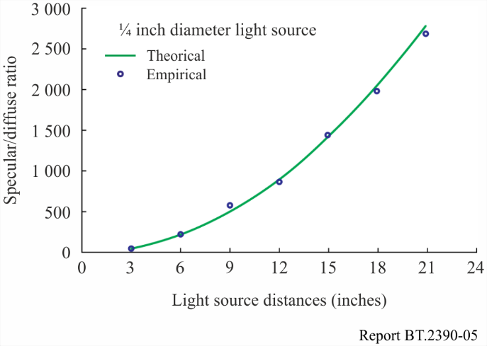
FIGURE 5 — Measurements showing that the specular regions can be over 1 000x higher in comparison to the underlying diffuse surface. After Wolff (1994)
图 5. 实测显示镜面区的亮度可比其下的漫反射表面高出 1 000 倍以上。据 Wolff(1994)。
With traditional imaging’s under-representation of highlight ranges, the question arises: what happens to the luminances of highlights? Figure 6 shows example scanlines of common distortions from a specular highlight from a glossy object, (b). It exceeds the maximum luminance of the display (or the signal), indicated as the dashed line titled ‘Target Max.’. Illustration (c) shows a distortion that is seldom selected, that is, to renormalize the entire range. Another approach, (d) preserves diffuse luminances, and the highlight is simply truncated (hard-clipping). Details within the highlight region are replaced with constant values, giving rise to flat regions in the image, looking quite artificial. Typical best practices (e), have been referred to as soft-clipping, or a knee. Here the shape and internal details of the highlight are somewhat preserved, without flattened regions. HDR allows for a result closer to scanline (b). The more accurate presentation of specular highlights, (assuming the entire video pathway is also HDR), is one of the key distinctions of HDR. A number of perceptual papers have looked closely at specular reflection, as mentioned in the beginning of this section. Preferences of luminances for diffuse white and highlights are shown in Fig. 3.
既然传统成像没能充分表现高光范围,问题就来了:高光的亮度究竟会怎样?图 6 以扫描线为例,展示了来自光泽物体的镜面高光(b)所产生的几种常见失真。该高光超过了显示设备(或信号)的最大亮度,即标有“目标最大值(Target Max.)”的虚线。图(c)所示的失真很少有人采用,即把整个范围重新归一化。另一种做法(d)保留漫反射亮度,而把高光直接截断(硬削波):高光区内的细节被替换为恒定值,使图像出现平板区域,看上去相当不自然。典型的最佳做法(e)被称为软削波或拐点:此时高光的形状和内部细节得到一定保留,没有平板区域。HDR 能得到更接近扫描线(b)的结果。更准确地呈现镜面高光(前提是整条视频通路也是 HDR),是 HDR 的关键区别之一。如本节开头所述,已有若干感知方面的论文对镜面反射作过细致研究。漫反射白与高光的亮度偏好见图 3。
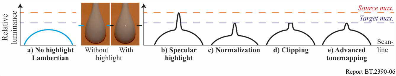
FIGURE 6 — Effects of highlight rendering, clipping and (tonescale) compression
图 6. 高光的渲染、削波与(色调比例)压缩所产生的效果。
Per the results shown in Fig. 3, 16% of the viewers preferred highlights ≥10 000 cd/m2. Also shown is that 50% of the viewers preferred diffuse white levels ≥ 600 cd/m2. This suggests that if display luminances increase in the future, some PQ content (e.g. outdoor scene in bright sun) may be produced with diffuse white levels higher than the levels indicated in Report ITU-R BT.2408. Consideration would, however, need to be given to the appearance on lower peak luminance PQ displays.
根据图 3 的结果,16% 的观众偏好高光达到 10 000 cd/m² 或更高;同时,50% 的观众偏好漫反射白电平达到 600 cd/m² 或更高。这表明,若未来显示亮度提升,某些 PQ 内容(如阳光强烈的室外场景)的漫反射白电平可能高于报告 ITU-R BT.2408 所给出的数值。不过,届时仍须考虑这些内容在峰值亮度较低的 PQ 显示设备上的呈现效果。
2 Television system architecture
2 电视系统架构
2.1 The relationship between the OETF, the EOTF and the OOTF
2.1 OETF、EOTF 与 OOTF 之间的关系
This Report makes extensive use of the following terms:
OETF: the opto-electronic transfer function, which converts linear scene light into the video signal, typically within a camera.
EOTF: electro-optical transfer function, which converts the video signal into the linear light output of the display.
OOTF: opto-optical transfer function, which has the role of applying the ‘rendering intent’.
本报告将大量使用以下术语:
- OETF:光电转换函数,把线性的场景光转换为视频信号,通常在相机内完成。
- EOTF:电光转换函数,把视频信号转换为显示设备输出的线性光。
- OOTF:光光转换函数,负责施加“渲染意图”。
These functions are related, so only two of the three are independent. Given any two of them the third one may be calculated. This section explains how they arise in television systems and how they are related.
这三个函数彼此相关,故三者中只有两个是独立的。给定其中任意两个,便可算出第三个。本节说明它们如何在电视系统中产生,以及彼此之间的关系。
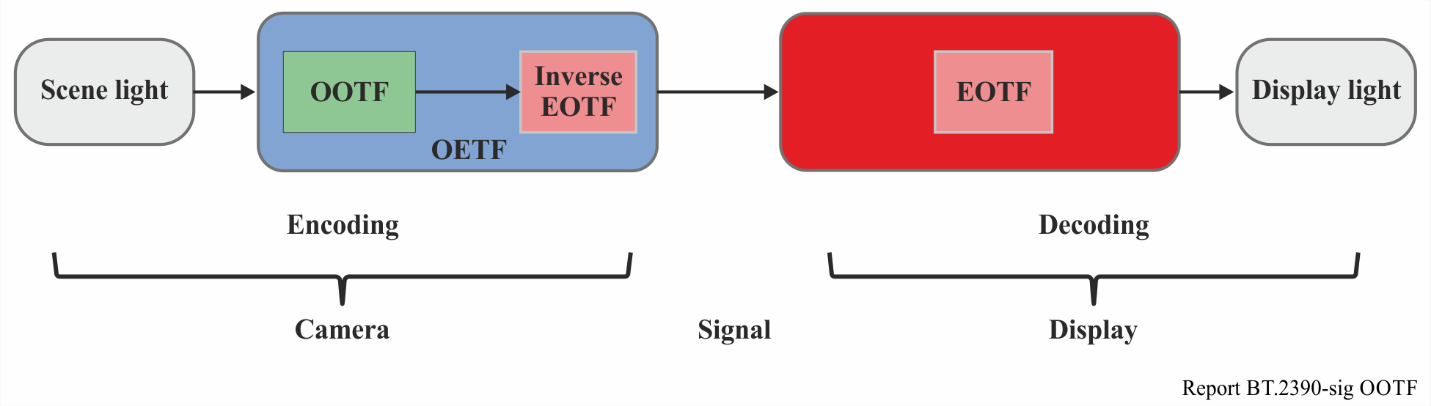
In television systems the displayed light is not linearly related to the light captured by the camera. Instead an overall non-linearity is applied, the OOTF. The ‘reference’ OOTF compensates for difference in tonal perception between the environment of the camera and that of the display. Specification and use of a ‘reference OOTF’ allow consistent end-to-end image reproduction, which is important in TV production.
在电视系统中,显示出的光与相机所采集的光并非线性关系,而是施加了一个总体的非线性变换,即 OOTF。“参考”OOTF 用来补偿相机环境与显示环境之间色调感知上的差异。规定并使用“参考 OOTF”,可实现端到端一致的图像还原,这在电视制作中很重要。
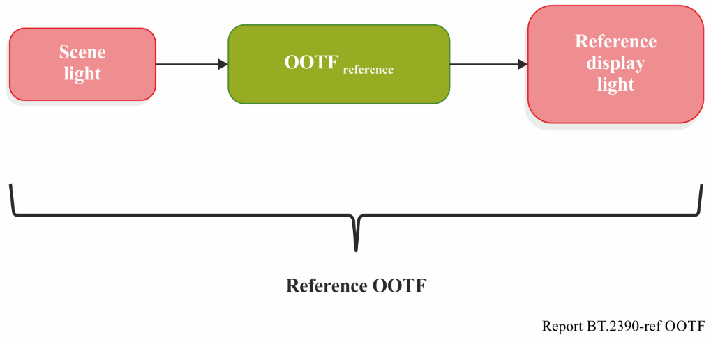
场景光(Scene light)→ OOTF_reference → 参考显示光(Reference display light);整段即“参考 OOTF(Reference OOTF)”。
概念图: 场景光经参考 OOTF 映射为参考显示光。
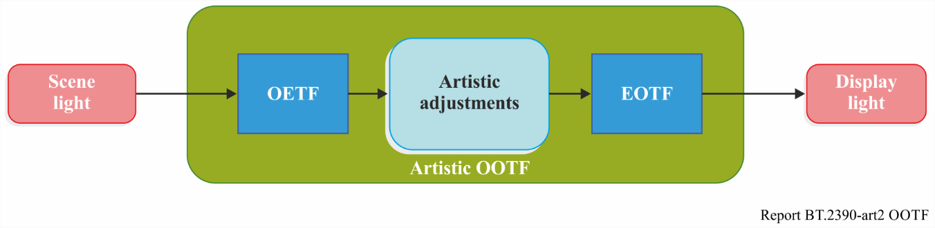
Artistic adjustment may be made to enhance the picture. These alter the OOTF, which may then be called the ‘artistic OOTF’. Artistic adjustment may be applied either before or after the reference OOTF.
为提升画面,可进行艺术性调整。这类调整会改变 OOTF,改变后的 OOTF 可称为“艺术 OOTF”。艺术性调整既可加在参考 OOTF 之前,也可加在其后。
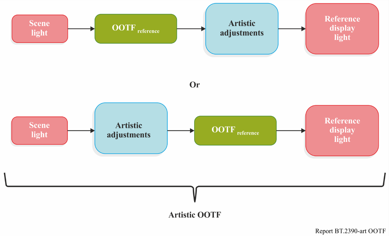
上行:场景光 → OOTF_reference → 艺术性调整(Artistic adjustments)→ 参考显示光;下行:场景光 → 艺术性调整 → OOTF_reference → 参考显示光。两者皆为“艺术 OOTF”。
概念图: 艺术性调整可置于参考 OOTF 之后(上行)或之前(下行),两种链路统称“艺术 OOTF”。
In general, the OOTF is a concatenation of the OETF, artistic adjustments, and the EOTF.
一般而言,OOTF 是 OETF、艺术性调整与 EOTF 三者串接而成的。
场景光 → OETF → 艺术性调整 → EOTF → 显示光;中间三段合起来即“艺术 OOTF”。
概念图: OOTF 由 OETF、艺术性调整与 EOTF 串接构成。
The PQ system was designed with the model shown below, where the OOTF is considered to be in the camera (or imposed in the production process):
PQ 系统是按下图模型设计的,其中 OOTF 被视为位于相机内(或在制作过程中施加):
场景光 →〔OETF:OOTF 串接 Inverse EOTF(编码/相机)〕→ 信号 → EOTF(解码/显示)→ 显示光。
概念图: PQ 系统模型——OOTF 位于相机端(包含在 OETF 内)。
The HLG system the system was designed with the model shown below, where the OOTF is considered to be in the display:
HLG 系统则按下图模型设计,其中 OOTF 被视为位于显示设备内:
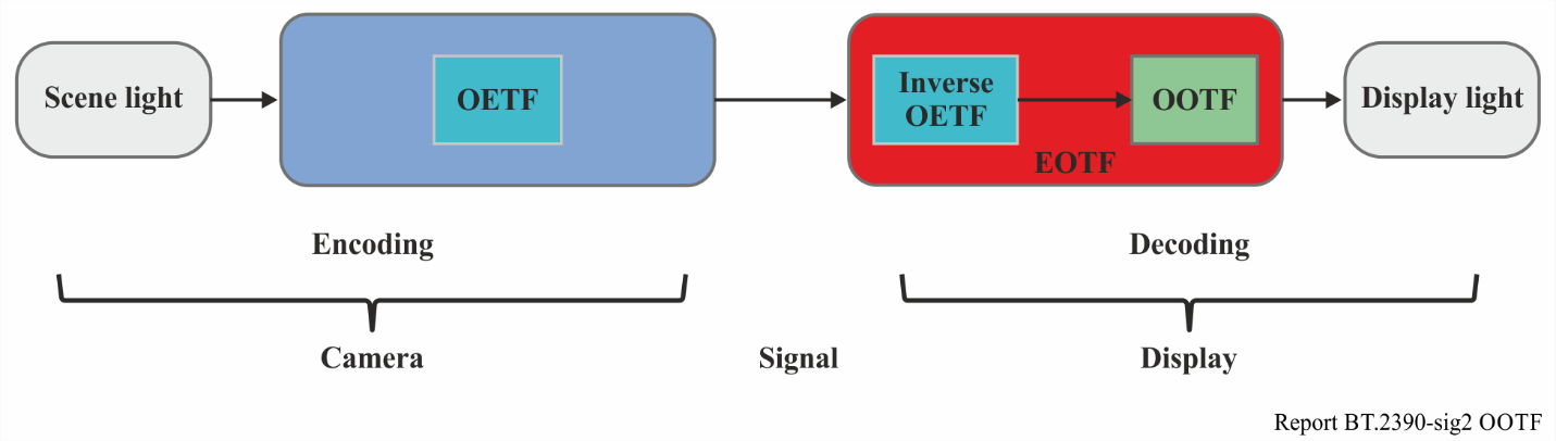
场景光 → OETF(编码/相机)→ 信号 →〔EOTF:Inverse OETF 串接 OOTF(解码/显示)〕→ 显示光。
概念图: HLG 系统模型——OOTF 位于显示端(包含在 EOTF 内)。
Only two of three non-linearities, the OETF, the EOTF, and the OOTF, are independent. In functional notation (where subscripts indicate the colour component):
OETF、EOTF、OOTF 这三个非线性函数中只有两个是独立的。用函数记法表示如下(下标表示颜色分量):
This is clearer if the symbol ∘ is used to represent concatenation. With this notation, the following three relationships between these three non-linearities can be obtained:
若用符号 ∘ 表示串接,关系会更清晰。用此记法可得到这三个非线性函数之间的如下关系:
The PQ approach is defined by its EOTF. For PQ the OETF may be derived from the OOTF using the third line of the equations above. In a complementary fashion the HLG approach is defined by its OETF. For HLG the EOTF may be derived from the OOTF using the second line of the equations above.
PQ 方案以其 EOTF 来定义。对 PQ 而言,可用上式第三行从 OOTF 推导出 OETF。与之互补,HLG 方案以其 OETF 来定义;对 HLG 而言,可用上式第二行从 OOTF 推导出 EOTF。
2.2 Conceptual TV system showing basic concepts
2.2 阐释基本概念的概念性电视系统
Figure 7 is a high level conceptual flow of a simplified television system that does not employ a non-linearity (such as gamma) in order to reduce the bit depth needed to represent the baseband signal; such a non-linearity is needed in signal pipelines that have limited bit depths (e.g. limitations to 8-12 bit values), but these pipelines will be considered later and the conceptual system described here is considered to have no such restrictions. In Fig. 7, the camera outputs a linear light signal, which is representative of the scene in front of the lens. Exposure controls (camera iris and filters) perform a global scaling, so the camera output is proportional to absolute scene light. The signal can be represented by high bit-depth integers, or for more efficiency, as 16-bit floating point. Non-reference viewing includes consumer viewing, as well as much TV production which often takes place in non-reference environments.
图 7 是一个简化电视系统的高层概念流程。该系统并未为压缩基带信号所需的位深而采用非线性变换(如伽马);在位深受限的信号通路(如限定为 8—12 比特)中确实需要这种非线性变换,但那类通路留待后文讨论,此处描述的概念性系统假定不受此类限制。图 7 中,相机输出线性光信号,它代表镜头前的场景。曝光控制(相机光圈和滤镜)执行全局缩放,因此相机输出与绝对场景光成正比。该信号可用高位深整数表示,或为提高效率用 16 比特浮点表示。非参考观看既包括消费者观看,也包括大量电视制作——后者往往就在非参考环境中进行。
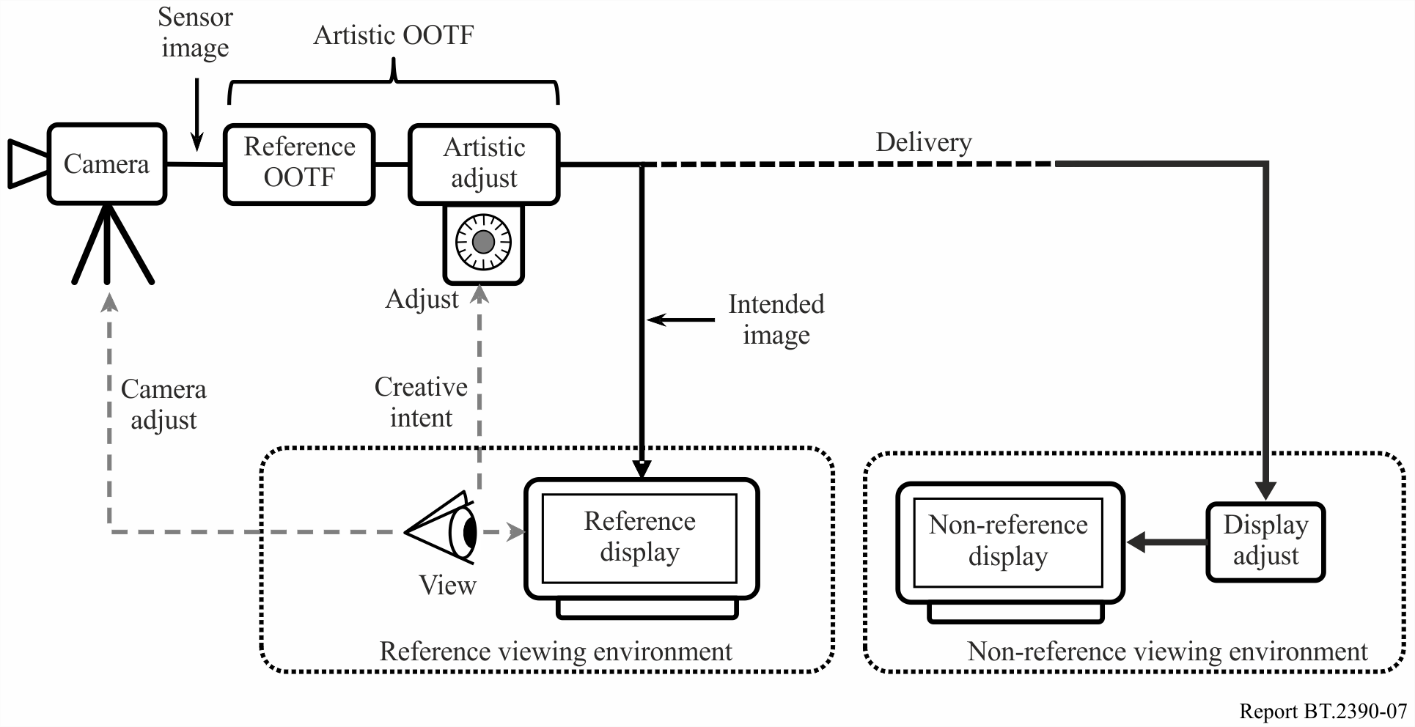
FIGURE 7 — The conceptual TV system
图 7. 概念性电视系统。
A linear display of the scene light would produce a low contrast washed out image as illustrated in Fig. 8. Therefore, the signal is altered to impose rendering intent, i.e. a Reference OOTF (opto-optical transfer function) roughly like that shown in Fig. 9. The sigmoid curve shown increases contrast over the important mid-brightness range, and softly clips both highlights and lowlights, thus mapping the possibly extremely high dynamic range present in many real world scenes to the dynamic range capability of the TV system.
若把场景光线性地显示出来,会得到一幅对比度低、发灰的图像,如图 8 所示。因此要对信号加以改造,以施加渲染意图,即一条大致如图 9 所示的参考 OOTF(光光转换函数)。图中的 S 形曲线在重要的中等亮度区提升对比度,并对高光和暗部都作软削波,从而把许多真实场景中可能极高的动态范围,映射到电视系统的动态范围能力之内。
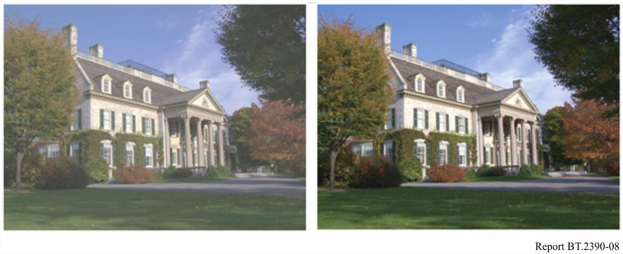
FIGURE 8 — The left image has a system transfer function (or greyscale) of unity slope. The right image has a system transfer function consistent with ITU broadcast practices
图 8. 左图的系统转换函数(即灰阶)斜率为 1;右图的系统转换函数符合 ITU 的广播实践。
A reference display in a reference viewing environment would, ideally, be used for viewing in production, and adjustments (e.g. iris) are made to the camera to optimize the image. Use of the Reference OOTF to produce images, with viewing done in the reference viewing environment, allows consistency of produced images across productions. If an artistic image ‘look’ different from that produced by the reference OOTF is desired for a specific programme, “Artistic adjust” may be used to further alter the image in order to create the image ‘look’ that is desired for that programme. Artistic adjustments may be made through the use of camera settings or after image capture during editing or in post-production. The combination of the reference OOTF plus artistic adjustments may be referred to as the ‘Artistic OOTF’.
理想情况下,制作时应在参考观看环境中用参考显示设备监看,并调整相机(如光圈)以优化图像。用参考 OOTF 来制作图像、并在参考观看环境中监看,可使不同制作之间所出图像保持一致。如果某档节目想要一种不同于参考 OOTF 所产生的艺术“调性”,可用“艺术调整”进一步改造图像,营造该节目所需的画面“调性”。艺术性调整既可通过相机设置实现,也可在图像采集之后于剪辑或后期阶段进行。参考 OOTF 与艺术性调整的组合可称为“艺术 OOTF”。
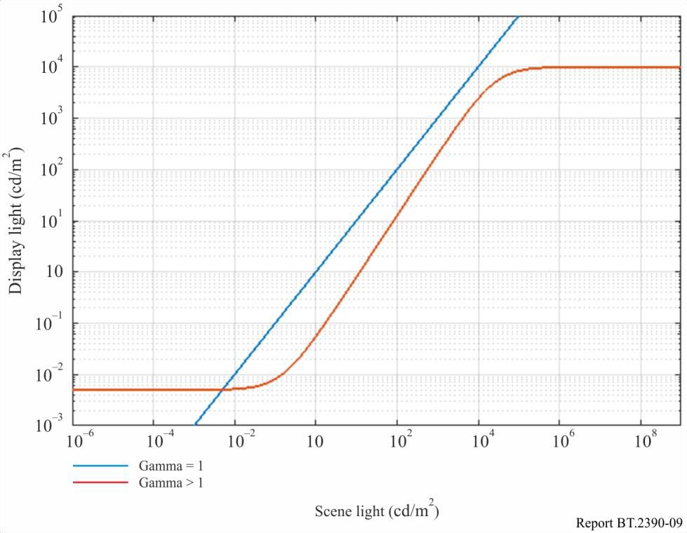
FIGURE 9 — Typical sigmoid used to map scene light to display light; extreme highlights and dark areas are compressed/clipped, the mid-range region employs a contrast enhancing gamma>1 characteristic
图 9. 用于把场景光映射为显示光的典型 S 形曲线;极端高光与暗部被压缩/削波,中段则采用增强对比度的伽马大于 1 的特性。
On the receive side where the consumer will view the image, if the consumer display is capable, and the consumer viewing environment is close to that of the reference viewing environment (dim room), then the consumer can view the image as intended. There may be limitations on both the viewing environment and the display itself. The viewing environment may be brighter than the reference environment, and the display may be limited in brightness, blackness, and/or colour gamut. Figure 7 shows ‘display adjust’ as an alteration made to accommodate these differences from the reference condition. To compensate for a brighter environment, display adjust may lift the black level of the signal. To accommodate limited brightness capability of the display, system gamma may be changed or a ‘knee’ may be imposed to roll off the highlights. To accommodate a limited colour gamut, gamut mapping would be performed to bring the wide gamut of colours in the delivered signal into the gamut that the display can actually show.
在消费者观看图像的接收端,如果消费者的显示设备能力足够,且观看环境接近参考观看环境(昏暗的房间),消费者就能看到符合创作意图的图像。观看环境和显示设备本身都可能存在局限:环境可能比参考环境更亮,显示设备在亮度、黑位和(或)色域上可能受限。图 7 中的“显示调整”就是为适应这些与参考条件的差异而作的改动。为补偿更亮的环境,显示调整可抬升信号的黑位;为迁就显示设备有限的亮度能力,可改变系统伽马或施加“拐点”以滚降高光;为迁就有限的色域,则进行色域映射,把所传信号中的宽色域色彩纳入显示设备实际能呈现的色域之内。
In practice television programmes are produced in a range of viewing environments using displays of varying capabilities. Thus, similar adjustments are often necessary in production displays to achieve consistency.
实际中,电视节目是在各种观看环境下、用能力各异的显示设备制作的。因此,为求一致,制作用显示设备往往也需要作类似的调整。
3 The legacy television architecture
3 传统电视架构
Since its beginning, television has employed restricted signal pipelines. Limited signal-to-noise ratios in the analogue days have transitioned to limited bit depths in the digital age. A non-linearity in the basic video signal was required in order to improve the visible signal-to-noise ratio in analogue systems, and the same non-linearity helps to prevent quantization artefacts in digital systems. This is the typical ‘gamma’ curve that is the natural characteristic of the CRT, and that is documented in Recommendations ITU-R BT.709, BT.1886 and BT.2020.
电视自诞生之日起就采用受限的信号通路。模拟时代受限的是信噪比,到了数字时代则转为受限的位深。在模拟系统中,为提高可见信噪比,基础视频信号必须带有一个非线性变换;同一个非线性变换在数字系统中又有助于防止量化伪影。这就是典型的“伽马”曲线,它本是 CRT 的固有特性,并被记载于建议书 ITU-R BT.709、BT.1886 和 BT.2020 中。
Until recently all displays were based on the CRT which, based on the common physics, all had a similar characteristic function converting the electrical signal to light, the so-called ‘electro-optical transfer function’ or EOTF. The camera characteristic of converting light into the electrical signal, the ‘opto-electronic transfer function’ or OETF, was adjusted to produce the desired image on the reference CRT display device. The combination of this traditional OETF and the CRT EOTF yielded the traditional OOTF. The non-linearity employed in legacy television systems (Recommendations ITU-R BT.601, BT.709 and BT.2020) is satisfactory in that 10-bit values are usable in production and 8-bit values are usable for delivery to consumers; this is for pictures with approximately 1 000:1 dynamic range5, i.e. 0.1 to 100 cd/m2.
直到不久前,所有显示设备都基于 CRT;由于物理原理相同,它们把电信号转换为光的特性函数都相近,即所谓“电光转换函数”(EOTF)。相机把光转换为电信号的特性,即“光电转换函数”(OETF),则经过调整,以便在参考 CRT 显示设备上产生理想的图像。这种传统 OETF 与 CRT EOTF 的组合,便得到传统 OOTF。传统电视系统(建议书 ITU-R BT.601、BT.709 和 BT.2020)所采用的非线性变换是令人满意的:制作环节可用 10 比特、面向消费者的分发可用 8 比特;这针对的是动态范围约为 1 000∶1(即 0.1 至 100 cd/m²)的画面[5]。
3.1 HDTV as specified in Recommendations ITU-R BT.709 and BT.1886
3.1 建议书 ITU-R BT.709 与 BT.1886 所规定的 HDTV
Recommendation ITU-R BT.709 explicitly specifies a reference OETF function that in combination with a CRT display produces a good image. Creative intent to alter this default image may be imposed in either the camera, by altering the OETF, or in post-production, thus altering the OOTF to achieve an ‘artistic’ OOTF. As the CRT is no longer manufactured, it became impractical to rely on the inherent CRT characteristic in order to achieve uniformity in reference displays. In the year 2011, Recommendation ITU-R BT.1886 was approved; this new Recommendation specified the EOTF of the reference display to be used for HDTV production; the EOTF specification is based on the CRT characteristics so that future monitors can mimic the legacy CRT in order to maintain the same image appearance in future displays. A reference OOTF is not explicitly specified for HDTV. Nevertheless, as shown in Fig. 10, in practice it exists as the cascade of the specified OETF (BT.709) and EOTF (BT.1886).
建议书 ITU-R BT.709 明确规定了一条参考 OETF 函数,它与 CRT 显示设备结合能产生良好的图像。若想改变这一默认图像以体现创作意图,可在相机端通过改变 OETF 实现,也可在后期通过改变 OOTF、得到一条“艺术”OOTF 来实现。由于 CRT 已停产,再靠 CRT 的固有特性来保证参考显示设备的一致性已不现实。2011 年,建议书 ITU-R BT.1886 获得批准;这部新建议书规定了 HDTV 制作所用参考显示设备的 EOTF。该 EOTF 规范以 CRT 特性为依据,使日后的监视器能够模仿传统 CRT,从而在未来的显示设备上保持相同的图像观感。HDTV 并未明确规定参考 OOTF。尽管如此,如图 10 所示,实际中它以所规定的 OETF(BT.709)与 EOTF(BT.1886)级联的形式存在。
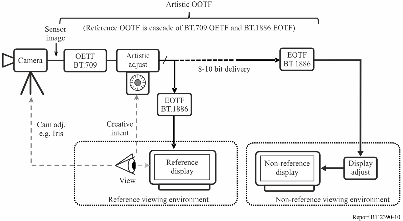
FIGURE 10 — The BT.709 HDTV television system architecture
图 10. BT.709 HDTV 电视系统架构。
Figure 10 shows the HDTV system. The linear light is encoded into a non-linear signal using the OETF specified in Recommendation ITU-R BT.709. Creative intent may be imposed by altering this encoding or in post-production by adjusting the signal itself; this can be considered as an alteration outside of the BT.709 OETF (e.g. as ‘artistic adjust’ in the diagram). Recommendation ITU-R BT.1886 specifies the conversion of the non-linear signal into display light. This drives the reference display in the reference viewing environment. The image on the reference display drives adjustment of the camera iris/exposure, and if desired, artistic adjust can alter the image to produce a different artistic look. At the receiver (ideally a reference display in a reference viewing environment) the non-linear signal is converted to display light using the Recommendation ITU-R BT.1886 specified function. There is typically further adjustment (display adjust) to compensate for viewing environment, display limitations, and viewer preference; this alteration may lift black level, effect a change in system gamma, or impose a ‘knee’ function to soft clip highlights. (In practice the EOTF gamma and display adjust functions may be combined into a single function.)
图 10 展示了 HDTV 系统。线性光用建议书 ITU-R BT.709 规定的 OETF 编码为非线性信号。可通过改变这一编码、或在后期调整信号本身来施加创作意图;这可看作 BT.709 OETF 之外的改动(如图中的“艺术调整”)。建议书 ITU-R BT.1886 规定了把非线性信号转换为显示光的方式,用以驱动参考观看环境中的参考显示设备。参考显示设备上的图像反过来指导相机光圈/曝光的调整;如有需要,艺术调整还可改造图像,营造不同的艺术调性。在接收端(理想情况是参考观看环境中的参考显示设备),非线性信号用建议书 ITU-R BT.1886 规定的函数转换为显示光。通常还会有进一步的调整(显示调整),以补偿观看环境、显示设备局限和观众偏好;这类改动可能抬升黑位、改变系统伽马,或施加“拐点”函数对高光作软削波。(实际中,EOTF 伽马与显示调整这两个函数可合并为单个函数。)
In a typical TV system the soft clipping of the highlights (sometimes known as the ‘shoulder’), described earlier and illustrated in Fig. 3, is implemented in the camera as a camera ‘knee’. This is part of the artistic adjustment of the image. Part of the low light portion of the characteristic (sometimes known as the ‘toe’) is implemented in the display as a black level adjustment. This adjustment takes place in the display as part of the BT.1886 EOTF and implements soft clipping of the lowlights.
在典型电视系统中,前文所述、并在图 3 中示意过的高光软削波(有时称为“肩部”),是在相机中以相机“拐点”的形式实现的,属于图像艺术性调整的一部分。特性曲线中低光段的一部分(有时称为“趾部”)则在显示设备中以黑位调整的形式实现:它作为 BT.1886 EOTF 的一部分在显示端进行,对暗部作软削波。
There is no clearly defined location of the reference OOTF in this system. The reference OOTF is the cascade of the OETF and the EOTF, and the actual OOTF is the cascade of those plus the artistic and display adjustments. Any deviation from the reference OOTF for reasons of creative intent must occur upstream of delivery. Alterations to compensate for the display environment or display characteristics must occur at the display by means of display adjust (or a modification of the EOTF away from the reference EOTF).
在这个系统中,参考 OOTF 并没有明确界定的位置。参考 OOTF 是 OETF 与 EOTF 的级联,而实际 OOTF 则是在此基础上再加上艺术调整和显示调整。任何出于创作意图、对参考 OOTF 的偏离,都必须发生在分发之前;而为补偿显示环境或显示特性所作的改动,则必须在显示端通过显示调整(或令 EOTF 偏离参考 EOTF)来完成。
4 RGB floating point HDR-TV system
4 RGB 浮点 HDR-TV 系统
A 16-bit RGB HDR system is defined for use when 48-bit/pixel pipelines are available. This architecture is shown in Fig. 11.
当具备每像素 48 比特的信号通路时,可使用所定义的 16 比特 RGB HDR 系统。该架构如图 11 所示。
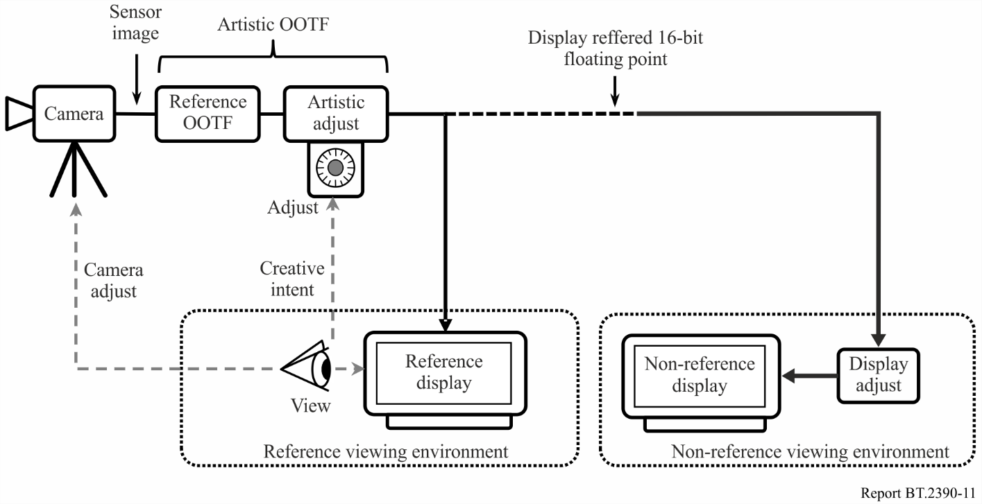
FIGURE 11 — HDR floating point system
图 11. HDR 浮点系统。
The raw output of the camera is a relative scene referred floating point signal. These floating point values may be scaled such that maximum diffuse white results in R = G = B = 1.0. The reference OOTF is implemented directly after camera capture of the scene, and an artistic adjustment may be used to make additional changes as desired for creative intent. Alternatively, the raw camera output can be used as input to a post-production process. The display referred output of the OOTF block (or post-production) is in the 16-bit floating point format which allows for adequate precision even for large colour volumes. Display referred floating point values directly represent light values on the display, i.e. R = G = B = 1.0 means 1.0 cd/m2 of white for a pixel. As before, display adjust is used to compensate as much as possible for limitations of displays, and for environments that may differ from the reference viewing environment that was (ideally) used during programme production.
相机的 RAW 输出是一种相对的、场景参考的浮点信号。可对这些浮点值缩放,使最大漫反射白对应 R = G = B = 1.0。参考 OOTF 紧接在相机采集场景之后施加,并可视创作意图用艺术性调整再作改动。另一种做法是把相机的 RAW 输出作为后期处理流程的输入。OOTF 模块(或后期)输出的是显示参考的 16 比特浮点信号,即便面对很大的色彩体积也能保持足够精度。显示参考的浮点值直接代表显示设备上的光值,即 R = G = B = 1.0 表示该像素为 1.0 cd/m² 的白。与前面一样,显示调整用来尽量补偿显示设备的局限,以及与节目制作时(理想情况下)所用参考观看环境之间的差异。
5 PQ HDR-TV
5 PQ HDR-TV
5.1 PQ system architecture
5.1 PQ 系统架构
When bit-constrained pipelines are required for television production systems, then an HDR implementation very similar to the current HDTV system of Fig. 10 can be constructed. This implementation is shown in Fig. 12.
当电视制作系统需要位深受限的信号通路时,可构建一种与图 10 当前 HDTV 系统极为相似的 HDR 实现方案,如图 12 所示。
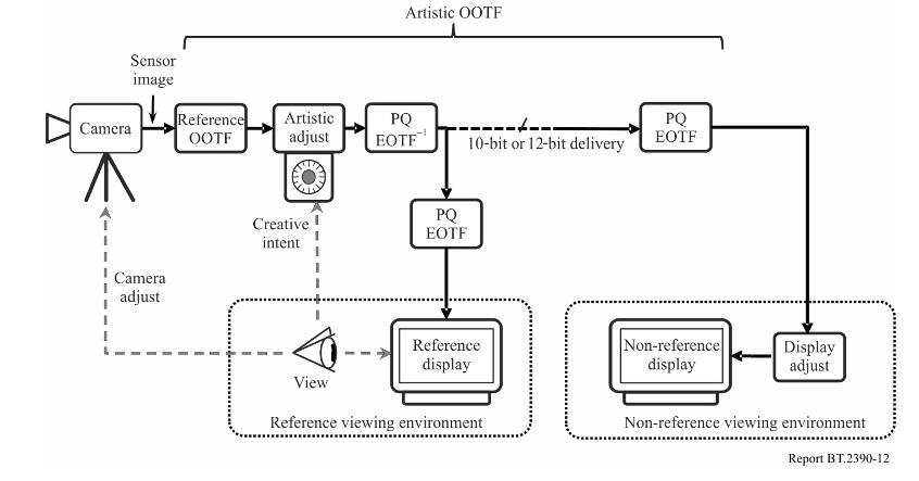
FIGURE 12 — PQ HDR-TV system with 10-bit or 12-bit integer values
图 12. 采用 10 比特或 12 比特整数值的 PQ HDR-TV 系统。
An optimized non-linear signal representation is used so that 10-bit or 12-bit depth values can accommodate the larger colour volume of HDR; otherwise this system is very similar to the HDTV system in use today. The PQ EOTF replaces the BT.1886 function of SDR HDTV, and the corresponding PQ OETF replaces the BT.709 OETF as the default camera capture curve. Once again, an artistic adjustment may be used to further modify the creative intent of the image, and a display adjustment is used to adapt the signal for different display characteristics and display environments. No use of metadata is shown or required.
这里采用了一种经过优化的非线性信号表示,使 10 比特或 12 比特的位深足以容纳 HDR 更大的色彩体积;除此之外,该系统与今天在用的 HDTV 系统十分相似。PQ EOTF 取代了 SDR HDTV 的 BT.1886 函数,相应的 PQ OETF 则取代 BT.709 OETF,作为默认的相机采集曲线。同样,可用艺术调整进一步修改图像的创作意图,并用显示调整使信号适应不同的显示特性和显示环境。该系统既未使用、也不需要元数据。
5.2 Design of the PQ non-linearity
5.2 PQ 非线性的设计
The traditional gamma nonlinearities of Recommendations ITU-R BT.709 and ITU-R BT.1886 are unsatisfactory when stretched to the much larger dynamic ranges desired for future television productions.
建议书 ITU-R BT.709 与 ITU-R BT.1886 的传统伽马非线性,一旦拉伸到未来电视制作所期望的大得多的动态范围,便不再令人满意。
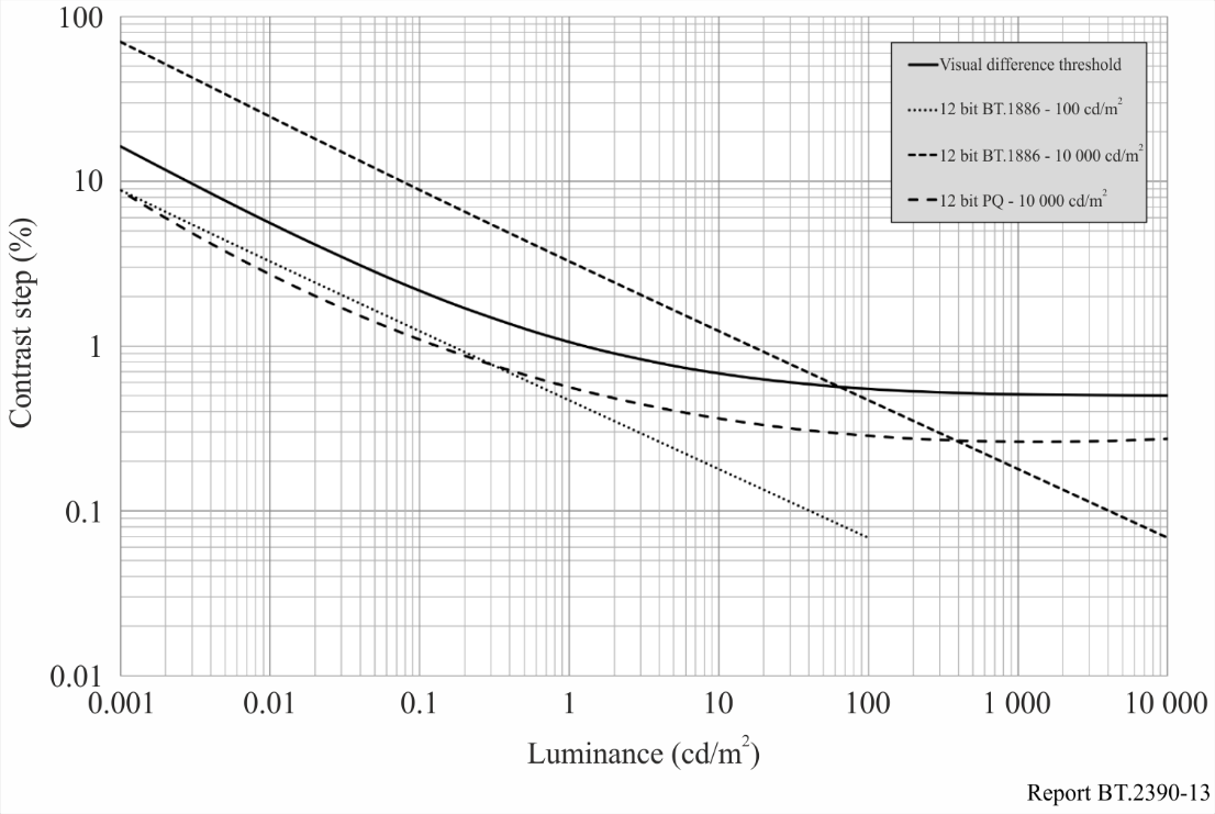
FIGURE 13 — Contrast step size vs. display luminance for 12 bit signals
图 13. 12 比特信号的对比度阶距随显示亮度的变化。
Figure 13 shows the approximate visual difference threshold as a solid black curve on a log-log plot with luminance on the x-axis and contrast step size (due to bit depth limitation) in % on the vertical axis. This threshold is based on the detailed Barten model of the human visual system. Lines which fall below this threshold curve will not exhibit any visible quantization artefacts such as image banding, while lines above the threshold curve may exhibit visual artefacts. While the legacy Recommendation ITU-R BT.1886 operating with a peak level of 100 cd/m2 is comfortably below the threshold curve when using 12-bit encoding, it rises substantially above the visual threshold when operating with a 10 000 cd/m2 peak. A traditional “gamma” power function is not a good approximation for human vision over an extended range of luminance values (too many code words allocated to very bright regions and not enough allocated to dark regions). This inefficiency was not a serious problem with SDR systems due to their limited dynamic range, but when trying to represent HDR luminance ranges, an improved curve is required. By using the same Barten model as the visual threshold calculation itself, an optimized nonlinear function was developed for the PQ signal, which can operate over the entire range from 10 000 cd/m2 down to less than 0.001 cd/m2 without any visible quantization artefacts using 12-bit coding precision.
图 13 在一张双对数坐标图上以黑色实线给出近似的视觉差异阈值,横轴为亮度,纵轴为(因位深受限而产生的)对比度阶距,单位为百分比。该阈值基于人眼视觉系统的精细 Barten 模型。落在阈值曲线以下的曲线不会出现任何可见的量化伪影(如图像条带),落在阈值曲线以上的则可能出现视觉伪影。传统建议书 ITU-R BT.1886 在 100 cd/m² 峰值、采用 12 比特编码时,舒适地处于阈值曲线之下;但若工作在 10 000 cd/m² 峰值,便会大幅升至视觉阈值之上。传统“伽马”幂函数在很宽的亮度范围内并不能很好地逼近人眼视觉(分配给极亮区的码字太多,分配给暗区的又不够)。由于 SDR 系统动态范围有限,这种低效尚不算严重问题;但要表示 HDR 的亮度范围,就需要一条改进的曲线。沿用与视觉阈值计算本身相同的 Barten 模型,便为 PQ 信号设计出一条经过优化的非线性函数;它能在从 10 000 cd/m² 一直到低于 0.001 cd/m² 的整个范围内工作,以 12 比特编码精度而不出现任何可见的量化伪影。
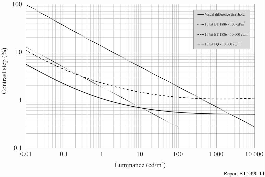
FIGURE 14 — Contrast step size vs. display luminance for 10-bit signals
图 14. 10 比特信号的对比度阶距随显示亮度的变化。
Figure 14 shows the same plots as Fig. 13 but with all three systems using 10-bit quantization. Though the signal lines all come above the threshold curve to some extent, experience has shown that with realistic camera noise levels, the slight quantization artefacts predicted for 100 cd/m2 Recommendation ITU-R BT.1886 or 10 000 cd/m2 PQ are masked and thus do not present real problems in television production.
图 14 与图 13 是同一组曲线,只是三套系统都改用 10 比特量化。尽管各信号曲线都在一定程度上升到阈值曲线之上,但经验表明:在真实的相机噪声水平下,对 100 cd/m² 的建议书 ITU-R BT.1886 或 10 000 cd/m² 的 PQ 所预测的轻微量化伪影会被掩盖,因而在电视制作中不会造成实际问题。
5.3 OOTF and OETF
5.3 OOTF 与 OETF
This subsection describes the PQ opto-optical transfer function (OOTF) and the resulting opto-electronic transfer function (OETF). The PQ opto-optical transfer function is normatively specified in Recommendation ITU-R BT.2100, which is intended to be compatible with existing SDR BT.709 signal sources and BT.1886 compliant displays. This maximizes compatibility for mixed source applications wherein some sources are HDR and some are SDR. It is desired that the image from an SDR source and that from an HDR source match everywhere the HDR image brightness overlaps the range of the SDR source (the HDR OOTF extends up to the maximum PQ displayed light level of 10 000 cd/m2).
本小节描述 PQ 光光转换函数(OOTF)及由它得出的光电转换函数(OETF)。PQ 光光转换函数在建议书 ITU-R BT.2100 中作规范性规定,其设计意图是与现有的 SDR BT.709 信号源以及符合 BT.1886 的显示设备兼容。这使得在部分源为 HDR、部分源为 SDR 的混合源应用中,兼容性达到最大。所期望的是:在 HDR 图像亮度与 SDR 源范围重叠的所有地方,来自 SDR 源的图像与来自 HDR 源的图像都能匹配(HDR OOTF 一直延伸到 PQ 显示光的最大电平 10 000 cd/m²)。
5.3.1 Generalized OOTF from Recommendation ITU-R BT.1886 in combination with Recommendation ITU-R BT.709
5.3.1 由建议书 ITU-R BT.1886 与 ITU-R BT.709 组合得出的广义 OOTF
In order to maximize compatibility with existing SDR signals, it is desired an OOTF consistent with the effective OOTF of existing practice which is:
为最大限度兼容现有 SDR 信号,需要一条与现有实践的有效 OOTF 相一致的 OOTF,即:
It is only needed to extend the range of OETF709 and EOTF1886 for HDR. The extension factor for displayed light is 10 000 / 100 = 100. As the SDR OOTF has a roughly gamma = 1.2 characteristic at the high end, the extension relative to scene light (the input to OOTF) is approximately 100 1/1.2 = 46.42. When the exact equations for Recommendations ITU-R BT.709 and ITU-R BT.1886 are used, the extension for HDR is 59.5208.
为适配 HDR,只需扩展 OETF₇₀₉ 与 EOTF₁₈₈₆ 的范围即可。显示光的扩展系数为 10 000 / 100 = 100。由于 SDR OOTF 在高端大致具有伽马 = 1.2 的特性,相对于场景光(OOTF 的输入)的扩展约为 100^(1/1.2) = 46.42。若采用建议书 ITU-R BT.709 与 ITU-R BT.1886 的精确公式,则 HDR 的扩展系数为 59.5208。
To expand the range of OETF709 to G709 for HDR the equation is therefore (HDR E normalized to range of 0 to 1):
因此,为 HDR 把 OETF₇₀₉ 的范围扩展为 G₇₀₉,公式如下(HDR 的 E 归一化到 0 至 1 的范围):
Consequently, the range of E′ is [0, 6.813] for HDR while it remains [0,1] for SDR. To expand the range of EOTF1886 to G1886 for HDR no change to the equation is necessary, the argument is simply allowed to extend to 6.813 (from 1) and hence the range increases from 100 to 10 000:
于是,E′ 的范围对 HDR 为 [0, 6.813],对 SDR 则仍为 [0, 1]。为 HDR 把 EOTF₁₈₈₆ 的范围扩展为 G₁₈₈₆ 无须改动公式,只要允许自变量从 1 延伸到 6.813,输出范围便从 100 增大到 10 000:
These extensions satisfy the boundary conditions:
a) E = 1 produces a displayed luminance of 10 000 cd/m2
b) E = 1/(59.5208) produces a displayed luminance of 100 cd/m2
The resulting OOTF is shown in Fig. 15. The x-axis, relative scene light is the same as E for SDR while for HDR it is 59.5208 × E since the domain of E is [0,1]:
这些扩展满足如下边界条件:
a) E = 1 产生 10 000 cd/m² 的显示亮度;
b) E = 1/(59.5208) 产生 100 cd/m² 的显示亮度。
由此得到的 OOTF 见图 15。横轴为相对场景光:对 SDR 而言它就等于 E,对 HDR 而言由于 E 的定义域为 [0, 1],故横轴为 59.5208 × E。
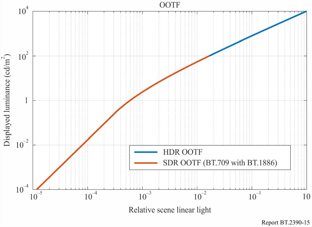
FIGURE 15 — PQ and SDR OOTF
图 15. PQ 与 SDR 的 OOTF。
5.3.2 Actual OOTFs from manually graded content
5.3.2 来自人工调色内容的实际 OOTF
It is instructive to compare this proposal with the actual OOTFs that are imposed when manually grading camera RAW output. The OOTF is the ratio of the graded linear output to the RAW linear input. Figure 16 shows several examples from the HDR sequence “Fantasy Flights”:
把上述方案与人工调色相机 RAW 输出时实际施加的 OOTF 作对比,颇有启发。这里的 OOTF 就是调色后线性输出与 RAW 线性输入之比。图 16 给出取自 HDR 片段《Fantasy Flights》的几个例子:
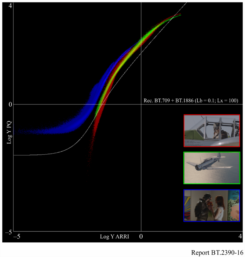
FIGURE 16 — Extracted OOTFs from Fantasy Flights (3 of 3)
图 16. 从《Fantasy Flights》中提取的 OOTF(共 3 例)。
These Figures show scatter plots of the log of the output luminance derived from the PQ grade versus the log of the relative input luminance derived from the ARRI RAW camera output. These scatter plots are colour-coded (RGB) to match the images shown in the lower right corner of each Figure. For comparison, the OOTF from the combination of Recommendations ITU-R BT.1886 and ITU-R BT.709 are plotted in white. This shows that the extracted OOTFs are, as one would expect, a bit brighter than SDR. Some preliminary conclusions can be drawn from this experimental data:
这些图以散点图形式,绘出由 PQ 调色得到的输出亮度对数,与由 ARRI 相机 RAW 输出得到的相对输入亮度对数之间的关系。散点按 RGB 着色,与各图右下角所示图像相对应。作为对比,由建议书 ITU-R BT.1886 与 ITU-R BT.709 组合得出的 OOTF 以白色绘出。可以看到,正如预料的那样,提取出的 OOTF 比 SDR 略亮。从这些实验数据可得出一些初步结论:
1 For this manually graded content, the OOTF is not a straight line, and thus the actual OOTF does not correspond to an overall “system gamma”.
2 Darker indoor scenes tend to be noise limited at the bottom end and the OOTF exhibits a very clear toe.
3 The extracted OOTFs appear to have roughly the same curvature in the mid-tones as the proposed model.
- 对这些人工调色的内容而言,OOTF 不是一条直线,因此实际 OOTF 并不对应某个总体的“系统伽马”。
- 较暗的室内场景在低端往往受噪声限制,OOTF 呈现出非常清晰的趾部。
- 提取出的 OOTF 在中间调的弯曲程度,与所提模型大致相同。
5.3.3 Resultant OETF
5.3.3 由此得出的 OETF
This OOTF can be combined with the inverse of the EOTF to produce an OETF. That OETF is shown in Fig. 17.
把这条 OOTF 与 EOTF 的逆相组合,即可得出一条 OETF,如图 17 所示。
In actual cameras there is noticeable noise at low signal levels, and in practice the OETF slope at low levels is limited so as to ‘crush’ the noise in black, thereby putting a ‘toe’ into the response. The reference OETF does not have such a ‘toe’, but one is apparent in the OOTF plot for the indoor scene of “Fantasy Flights” shown above.
实际相机在低信号电平处有明显噪声,因此实践中会限制 OETF 在低电平段的斜率,把噪声“压”进黑里,从而在响应中加入一段“趾部”。参考 OETF 本身没有这样的“趾部”,但在上文《Fantasy Flights》室内场景的 OOTF 曲线中可以明显看到。
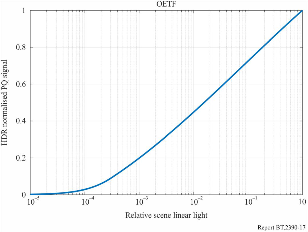
FIGURE 17 — HDR OETF
图 17. HDR OETF。
This OETF:
– emulates the ‘look’ of Recommendation ITU-R BT.709 plus Recommendation ITU-R BT.1886 for display light up to the limit of SDR;
– facilitates mixing of legacy BT.709 signals and PQ HDR signals;
– offers reasonable behaviour for levels above those of SDR.
这条 OETF:
- 在显示光不超过 SDR 上限的范围内,仿照建议书 ITU-R BT.709 加 ITU-R BT.1886 的“调性”;
- 便于把传统 BT.709 信号与 PQ HDR 信号混合使用;
- 对高于 SDR 的电平给出合理的表现。
5.4 Display mapping
5.4 显示映射
The PQ HDR system generates content that is optimum for viewing on a reference monitor in a reference viewing environment. The reference monitor would ideally be capable of accurately rendering black levels down to or below 0.005 cd/m2 and highlights up to 10 000 cd/m2. Also, the ideal monitor would be capable of showing the entire colour gamut within the BT.2020 triangle. The viewing environment would ideally be dimly lit, with the area surrounding the monitor being a neutral grey (6 500 degree Kelvin) at a brightness of 5 cd/m2. However, content often must be viewed or produced in environments brighter than the reference condition, and on monitors that cannot display the deepest blacks or brightest highlights that the PQ signal can convey. In these cases, the display characteristic needs to be changed in a process often referred to as display mapping (DM). More information can be found in Recommendation ITU-R BT.814 and Reports ITU-R BT.2408 and ITU-R BT.2446.
PQ HDR 系统所生成的内容,最适合在参考观看环境中、用参考监视器观看。理想的参考监视器应能准确还原低至或低于 0.005 cd/m² 的黑位,以及高至 10 000 cd/m² 的高光;还应能呈现 BT.2020 三角形内的全部色域。理想的观看环境应光线昏暗,监视器周边为中性灰(色温 6 500 K)、亮度 5 cd/m²。然而,内容往往不得不在比参考条件更亮的环境中观看或制作,且所用监视器无法显示 PQ 信号所能传达的最深的黑或最亮的高光。遇到这些情况,就需要改变显示特性,这一过程通常称为显示映射(DM)。更多信息见建议书 ITU-R BT.814 以及报告 ITU-R BT.2408 和 ITU-R BT.2446。
6 HLG HDR-TV
6 HLG HDR-TV
The hybrid log-gamma (HLG) HDR-TV signal parameters were designed from the outset to offer broadcasters and programme producers an evolutionary approach to HDR production and distribution. The signal characteristic is similar to that of a traditional standard dynamic range camera with a ‘knee’ and requires no production metadata. It is therefore compatible with conventional standard dynamic range production equipment, tools and infrastructure. Furthermore, the HLG HDR-TV signal parameters were designed to provide a significant degree of compatibility on BT.2020 colour SDR displays (see § 6.4). Thus HDR monitors are only necessary in critical monitoring areas. The design of the HLG HDR signal parameters is intended to allow distribution networks to provide a single HEVC Main 10 bitstream that can target both SDR and HDR receivers, where those SDR receivers support the BT.2020 colour container (e.g. DVB and ARIB HEVC UHD receivers).
混合对数伽马(HLG)HDR-TV 信号参数从一开始就着眼于为广播机构和节目制作者提供一条循序渐进的 HDR 制作与分发路径。其信号特性类似于带“拐点”的传统标准动态范围相机,且无须制作元数据。因此它与常规标准动态范围的制作设备、工具和基础设施兼容。此外,HLG HDR-TV 信号参数在设计上还能在 BT.2020 色彩的 SDR 显示设备上提供相当程度的兼容性(见 6.4 节)。因此,只有在关键监看区才需要 HDR 监视器。HLG HDR 信号参数的设计意图是:让分发网络只需提供单一一路 HEVC Main 10 码流,便能同时面向 SDR 和 HDR 接收机,前提是那些 SDR 接收机支持 BT.2020 色彩容器(如 DVB 和 ARIB 的 HEVC UHD 接收机)。
6.1 The hybrid log-gamma opto-electronic transfer function (OETF)
6.1 混合对数伽马光电转换函数(OETF)
In the brighter parts and highlights of an image the threshold for perceiving quantization is approximately constant (known as Weber’s law). This implies a logarithmic OETF would provide the maximum dynamic range for a given bit depth. Proprietary logarithmic OETFs are in widespread use. But in the low lights it becomes increasingly difficult to perceive banding. That is, the threshold of visibility for banding becomes higher as the image gets darker. This is known as the De Vries-Rose law. The conventional gamma OETF used for SDR comes close to matching the De Vries-Rose law, which is perhaps not coincidental since gamma curves were designed for dim CRT displays. So an ideal OETF might be logarithmic in the high tones and a gamma law in the low lights, which is essentially the form of the hybrid log-gamma OETF.
在图像较亮的部分和高光中,感知量化的阈值近似恒定(即韦伯定律)。这意味着,在给定位深下,对数型 OETF 能提供最大的动态范围。各家专有的对数型 OETF 已被广泛使用。但在暗部,条带越来越难以察觉,也就是说,图像越暗,条带的可见阈值越高,这称为德弗里斯-罗斯定律(De Vries-Rose law)。SDR 所用的常规伽马 OETF 与德弗里斯-罗斯定律相当接近,这或许并非巧合,因为伽马曲线本就是为昏暗的 CRT 显示设备设计的。因此,理想的 OETF 也许应在高调段为对数、在暗部为伽马律——这正是混合对数伽马 OETF 的基本形态。
The dynamic range of modern video cameras is considerably greater than can be conveyed by a video signal using a conventional OETF gamma curve (e.g. Recommendation ITU-R BT.709 or Recommendation ITU-R BT.2020). In order to exploit their full dynamic range conventional video cameras sometimes use a ‘knee’ characteristic to extend the dynamic range of the signal. The knee characteristic compresses the image highlights to prevent the signal from clipping or being ‘blown out’ (overexposed). Knee characteristics are discussed, for example, in “Circles of Confusion”, by Alan Roberts, published by the EBU. The ‘shoulder’ characteristic of conventional photochemical film used in movie cameras provides a similar effect. When a hybrid log gamma HDR video signal is displayed on a conventional SDR display the effect is similar to the use of a digital camera with a knee or using film. It is not surprising therefore, that the HLG video signal is highly compatible with conventional SDR displays, because what you see is very similar to the signal from an SDR camera. Indeed the ‘knee’ characteristic of the HLG OETF, defined in Table 5 of Recommendation ITU-R BT.2100 (and shown in Fig. 18 below), provides an extended highlight range that is comparable to some ‘knees’ used for SDR. Note that the ‘knee’ curve in the Figure is diagrammatic for illustrative purposes only. Whilst knees are sometimes described in the literature as linear, as in this Figure, in practice they are ‘smooth’ and avoid the discontinuous gradient shown here, which can result in objectionable colour shifts.
现代摄像机的动态范围,远大于用常规 OETF 伽马曲线(如建议书 ITU-R BT.709 或 ITU-R BT.2020)的视频信号所能传达的范围。为发挥其全部动态范围,常规摄像机有时会用“拐点”特性来扩展信号的动态范围。拐点特性压缩图像高光,防止信号被削波或“过曝”(曝光过度)。关于拐点特性的讨论,可参见 EBU 出版、Alan Roberts 所著的《Circles of Confusion》。电影摄影机所用常规感光胶片的“肩部”特性也能产生类似效果。当混合对数伽马 HDR 视频信号显示在常规 SDR 显示设备上时,其效果类似于使用带拐点的数字相机或使用胶片。因此不难理解,HLG 视频信号与常规 SDR 显示设备高度兼容——因为你看到的画面与 SDR 相机的信号非常相似。事实上,HLG OETF 的“拐点”特性(在建议书 ITU-R BT.2100 表 5 中定义,并示于下方图 18)所提供的扩展高光范围,可与某些用于 SDR 的“拐点”相媲美。需要注意,图中的“拐点”曲线只是示意性的。文献中有时把拐点描述为线性(如本图),但实际中拐点是“平滑”的,会避免本图所示那种斜率不连续的折点——后者可能导致令人不快的色偏。
An HLG signal is defined as:
OETF: With E is normalized to the range [0:1] then the equation for the OETF is:
HLG 信号定义如下。
OETF:当 E 归一化到 [0, 1] 范围时,OETF 公式为:
where:
E: signal for each colour component {Rs, Gs, Bs} proportional to scene linear light and scaled by camera exposure, normalized to the range [0:1]
E´: resulting non-linear signal {R′, G′, B′} in the range [0:1].
a = 0.17883277, b = 1 − 4a, c = 0.5 − a·ln(4a)
式中:
- E:各颜色分量 {R_s, G_s, B_s} 的信号,正比于场景线性光并经相机曝光缩放,归一化到 [0, 1] 范围;
- E′:由此得出的非线性信号 {R′, G′, B′},取值范围 [0, 1]。
The HLG OETF is shown in Fig. 18 alongside the conventional SDR OETF and an (illustrative) knee characteristic. These plots assume that two cameras, one BT.2020 and the other BT.2100 (that is, one SDR and one HDR), are set up with the same sensitivity. For example, if both cameras were looking at the same 18% grey chart, then their sensitivities (gain, iris, and shutter time) could be adjusted so that the signal level was 42.5% of nominal full signal level for both cameras. A notional SDR ‘knee’ is shown on the same plot, with a breakpoint of 87.5% signal level, which extends the SDR dynamic capture range substantially.
图 18 将 HLG OETF 与常规 SDR OETF 以及一条(示意性的)拐点特性并列绘出。这些曲线假定有两台相机,一台为 BT.2020、另一台为 BT.2100(即一台 SDR、一台 HDR),并设为相同的灵敏度。例如,若两台相机都对着同一张 18% 灰卡,可调整其灵敏度(增益、光圈和快门时间),使两台相机的信号电平都为标称满信号电平的 42.5%。图中同时给出一条假想的 SDR“拐点”,折点在 87.5% 信号电平处,它大幅扩展了 SDR 的动态采集范围。
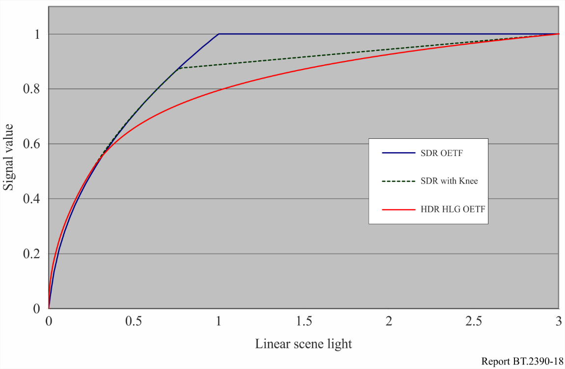
FIGURE 18 — Comparison of SDR and HLG HDR OETFs
图 18. SDR 与 HLG HDR OETF 的对比。
When the two cameras’ (SDR and HDR) sensitivities are equalized then both the SDR (BT.2020) and HDR responses to light amplitude would be almost the same for signal levels at or below 50%. Above 50% signal level the HDR OETF is logarithmic, which means it can capture higher light levels (such as specular reflections and highlights) without clipping. There are small differences between the two plots below 50% of nominal signal range. This is because SDR OETFs include a linear portion near black to avoid excessive noise amplification. HLG, by contrast, uses a pure square root OETF at low levels. This allows HLG to achieve higher dynamic range “in the blacks”, but it does mean that camera manufacturers must use an alternative to the linear part of the SDR OETF to avoid excessive noise amplification in the black.
当两台相机(SDR 与 HDR)的灵敏度调成一致时,在 50% 及以下的信号电平上,SDR(BT.2020)与 HDR 对光幅度的响应几乎相同。在 50% 信号电平以上,HDR OETF 为对数型,意味着它能采集更高的光电平(如镜面反射和高光)而不削波。在标称信号范围 50% 以下,两条曲线略有差异,这是因为 SDR OETF 在接近黑处含有一段线性区,以避免过度放大噪声;相比之下,HLG 在低电平采用纯平方根 OETF。这让 HLG 能在“黑部”获得更高的动态范围,但也意味着相机厂商必须用某种替代手段来取代 SDR OETF 的线性段,以避免在黑部过度放大噪声。
Note that the conventional ‘narrow range’ digital signal can actually support signal levels of up to 109% of nominal full scale. This is to accommodate overshoots and highlights. If this additional signal range is used (though not all equipment supports it) then even higher light levels may be captured without clipping.
需要注意,常规的“窄范围”数字信号实际上可支持高达标称满量程 109% 的信号电平,以容纳过冲和高光。若启用这段额外的信号范围(并非所有设备都支持),便能采集更高的光电平而不削波。
Considering a nominal full scale signal (i.e. 100% signal level), and with the cameras set up as above, then the SDR camera can capture objects no brighter than 100% reflective (i.e. no highlights). The HLG camera increases the luminance that can be captured by a factor of 3. If the signal is allowed to excurse to the maximum 109% range (super-whites) then SDR can capture luminance equivalent to 120% reflectivity, whereas HLG can capture nearly a factor of 5 more luminance than 100% reflectivity. It is the limitations in the ability of SDR displays to accurately render highlights that prompts the use of camera knees.
考虑标称满量程信号(即 100% 信号电平),并按上述方式架设相机,则 SDR 相机所能采集的物体亮度不超过 100% 反射率(即没有高光)。HLG 相机则把可采集的亮度提高到 3 倍。若允许信号摆动到 109% 的最大范围(超白),则 SDR 可采集相当于 120% 反射率的亮度,而 HLG 可采集的亮度接近 100% 反射率的 5 倍。正是由于 SDR 显示设备准确还原高光的能力有限,才促使人们使用相机拐点。
A naïve interpretation of these plots might suggest that the dynamic range of HLG is only three times greater than SDR, but this is not the case. HDR is about more than just increasing the brightness of highlights. Creating the detail in lowlights and ‘in the black’ is also very important and HLG adds much dynamic range here. Secondly, the OETF describes the capture dynamic range. The dynamic range on the display is greater because of overall system gamma, discussed below. With a typical system gamma of 1.2, and the camera sensitivity adjusted as described, HLG supports display highlights which are a factor of 3.7 (or 6.9 with super-whites) higher than diffuse white.
若对这些曲线作想当然的解读,可能以为 HLG 的动态范围只比 SDR 大 3 倍,其实不然。HDR 并不只是提高高光的亮度。营造暗部和“黑部”的细节同样十分重要,而 HLG 在这里增加了很多动态范围。其次,OETF 描述的是采集动态范围;由于下文将讨论的总体系统伽马,显示端的动态范围更大。在典型系统伽马 1.2、相机灵敏度按上述调整的情况下,HLG 所支持的显示高光比漫反射白高出 3.7 倍(启用超白时为 6.9 倍)。
However, the foregoing discussion assumes that ‘diffuse white’ produces 100% signal output for SDR cameras. Whilst this may be true for some programmes, the signal level for diffuse white is not defined for SDR signals. In practice it varies between about 90% and 115% depending on genre, geographical region, and artistic preference. Drama, in particular, tends to set diffuse white at a lower signal level. This supports more artistically pleasing pictures that can contain some highlight detail. HLG supports a much greater dynamic range than SDR, and can take advantage of this by setting diffuse white at a lower signal level to support more highlight dynamic range.
不过,上述讨论假定“漫反射白”在 SDR 相机上产生 100% 的信号输出。这对某些节目或许成立,但 SDR 信号并未定义漫反射白的信号电平。实际中,它视题材、地域和艺术偏好而在约 90% 至 115% 之间变动。尤其是剧情片,往往把漫反射白设在较低的信号电平上,从而获得在艺术上更悦目、又能保留一些高光细节的画面。HLG 支持的动态范围远大于 SDR,可以利用这一点,把漫反射白设在较低的信号电平上,以支持更大的高光动态范围。
Report ITU-R BT.2408 indicates that, for HLG HDR, diffuse white should be set at a signal level of 75%. This can be configured by making the output from an 18% grey card correspond to a signal level of 38%, rather than the 42.5% stated above. The OETFs for this camera setup are illustrated in Fig. 19 below, which also include the plots above for comparison. Setting 18% grey to 42.5% and 38% results in the diffuse white signal level being 100% and 89% respectively for SDR, and 79% and 75% respectively for HLG. The traces on the plots are labelled accordingly.
报告 ITU-R BT.2408 指出,对 HLG HDR 而言,漫反射白应设在 75% 的信号电平上。具体可通过让 18% 灰卡的输出对应 38% 的信号电平(而非上文所述的 42.5%)来实现。这种相机设置下的 OETF 见下方图 19,图中同时纳入上文的曲线以资比较。把 18% 灰分别设为 42.5% 与 38%,对 SDR 而言漫反射白的信号电平分别为 100% 与 89%,对 HLG 而言分别为 79% 与 75%。图中各曲线已相应标注。
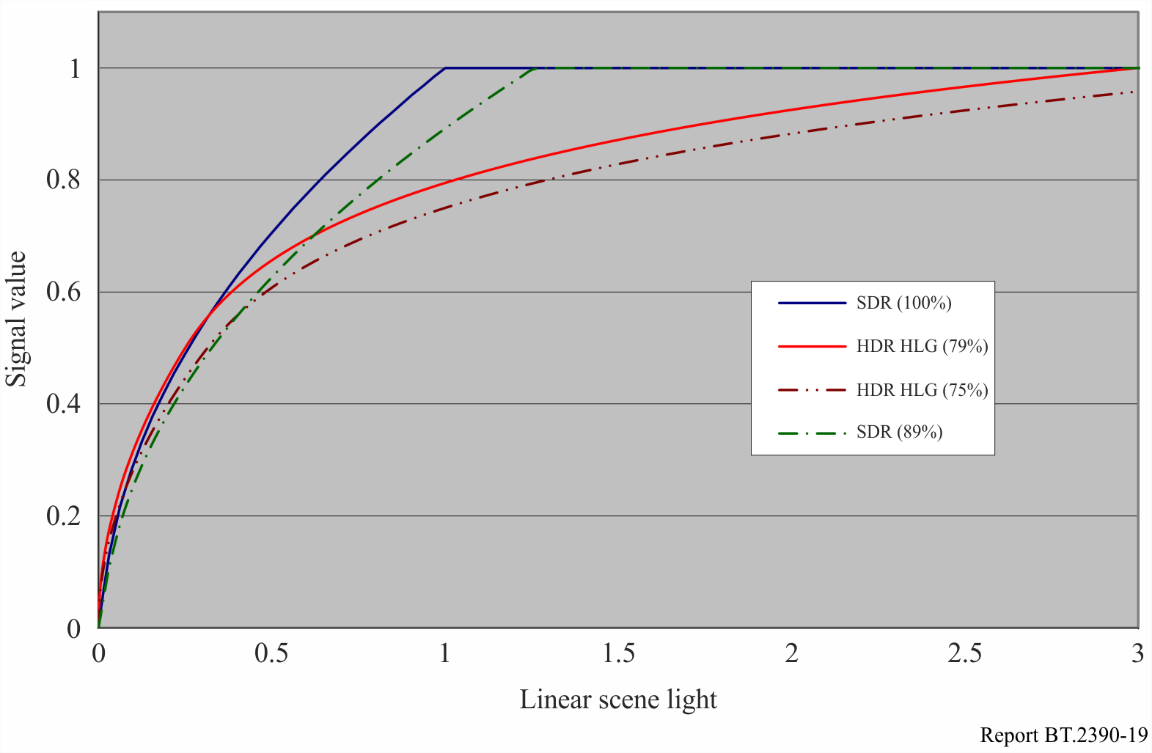
FIGURE 19 — Comparison of HLG OETFs with BT.2408 signal levels for diffuse white
图 19. HLG OETF 与 BT.2408 漫反射白信号电平的对比。
With cameras configured to produce this slightly lower signal level for diffuse white, the dynamic range available for highlights is increased. SDR can now support scene luminance equivalent to 125% of diffuse white, and HDR can support scene luminance of 375% diffuse white. These figures increase to 150% and about 620% if super-whites are used. So, the use of super-whites is much more advantageous for HLG than it is for SDR. Note that these figures increase further to 163% and 890% at the display when a typical system gamma of 1.2 is used.
把相机配置成让漫反射白产生这一略低的信号电平后,可用于高光的动态范围便增大了。此时 SDR 可支持相当于漫反射白 125% 的场景亮度,HDR 可支持漫反射白 375% 的场景亮度。若启用超白,这两个数值增至 150% 与约 620%。可见,超白对 HLG 远比对 SDR 更有利。需要注意,在采用典型系统伽马 1.2 时,这两个数值在显示端进一步增至 163% 与 890%。
6.2 System gamma and the opto-optical transfer function (OOTF)
6.2 系统伽马与光光转换函数(OOTF)
As is well known, and explained in § 2.2, the light out of a television display is not proportional to the light detected by the camera. The overall system non-linearity, or ‘rendering intent’ is defined by the opto-optical transfer function, or OOTF. The OOTF maps relative scene linear light to display linear light. Rendering intent is needed to compensate for the psychovisual effects of watching an emissive screen in a dark or dim environment, which affects the adaptation state (and hence the sensitivity) of the eye. Traditionally movies were, and often still are, shot on negative film with a gamma of about 0.6. They were then displayed from a print with a gamma of between 2.6 and 3.0. This gives movies a system gamma of between 1.6 and 1.8, which is needed because of the dark viewing environment. Conventional SDR television has an OOTF which is also a gamma curve with a system gamma of 1.2. But, for HDR, the brightness of displays and backgrounds/surround will vary widely, and the system gamma will need to vary accordingly.
正如众所周知、并已在 2.2 节解释过的,电视显示设备发出的光与相机所探测的光并不成正比。这一总体的系统非线性,即“渲染意图”,由光光转换函数(OOTF)定义。OOTF 把相对场景线性光映射为显示线性光。之所以需要渲染意图,是为了补偿在黑暗或昏暗环境中观看自发光屏幕所产生的心理视觉效应——它会影响眼睛的适应状态(进而影响其灵敏度)。传统上电影是用伽马约为 0.6 的负片拍摄的(如今也常如此),再用伽马在 2.6 至 3.0 之间的拷贝放映。这样电影的系统伽马便在 1.6 至 1.8 之间,而这正是黑暗观看环境所必需的。常规 SDR 电视的 OOTF 同样是一条伽马曲线,系统伽马为 1.2。但对 HDR 而言,显示设备和背景/周边的亮度会有很大变化,系统伽马也需随之变化。
Colour images consist of red, green and blue components and this affects how the OOTF should be applied. Simply applying a gamma curve to each component separately as is done for SDR television distorts the colour; in particular, it distorts saturation but also to a lesser extent the hue. As an illustration, suppose the red, green and blue components of a pixel have (normalized) values of (0.25, 0.75, 0.25). Applying a display gamma of 2, (i.e. squaring the value of the components) is obtained (0.062 5, 0.562 5, 0.062 5). In this example, the pixel has got slightly darker and the ratio of green to blue and red has increased (from 3:1 to 9:1). This means, a green pixel would have appeared as a discernibly different shade of green. This approach is far from ideal if it is wished to avoid distorting colours when they are displayed.
彩色图像由红、绿、蓝三个分量构成,这会影响 OOTF 应当如何施加。像 SDR 电视那样,简单地对每个分量分别施加一条伽马曲线,会使色彩失真:尤其是饱和度失真,色相也会在较小程度上失真。举例来说,设某像素的红、绿、蓝(归一化)分量为 (0.25, 0.75, 0.25),施加显示伽马 2(即对各分量取平方),得到 (0.0625, 0.5625, 0.0625)。此例中,像素略微变暗,绿对蓝、红的比值增大(从 3∶1 升至 9∶1)。这意味着一个绿色像素会呈现出明显不同的绿色色调。若希望在显示时不让色彩失真,这种做法远非理想。
Instead of the current SDR practice of applying a gamma curve independently to each colour component, for HDR it should be applied to the luminance alone. The luminance of a pixel is given by a weighted sum of the colour components; the weights depend on the colour primaries and the white point. According to Recommendation ITU-R BT.2100, luminance is given by:
对 HDR 而言,不应沿用当前 SDR 那种对每个颜色分量分别施加伽马曲线的做法,而应只对亮度施加伽马曲线。像素的亮度由各颜色分量的加权和给出,权重取决于基色和白点。根据建议书 ITU-R BT.2100,亮度为:
where YS represents normalized linear scene luminance and RS, GS and BS represent the normalized, linear scene light (i.e. before applying OETF) colour components. By applying rendering intent (OOTF) to the luminance component only it is possible to avoid colour changes in the display.
式中 Y_S 表示归一化的线性场景亮度,R_S、G_S、B_S 表示归一化的线性场景光(即施加 OETF 之前)颜色分量。只对亮度分量施加渲染意图(OOTF),便可避免显示时的色彩变化。
The HLG reference OOTF is therefore given by:
因此,HLG 参考 OOTF 为:
where:
FD: luminance of a displayed linear component {RD, GD, or BD}, in cd/m2
E: signal for each colour component {Rs, Gs, Bs} proportional to scene linear light and scaled by camera exposure, normalized to the range [0:1]
α: user adjustment for the luminance of the display, commonly known in the past as a “contrast control”. It represents LW, the nominal peak luminance of a display for achromatic pixels in cd/m2
γ: is an exponent, which varies depending on LW as described below, and which is equal to 1.2 at the nominal display peak luminance of 1 000 cd/m2.
式中:
- F_D:显示出的某个线性分量 {R_D、G_D 或 B_D} 的亮度,单位 cd/m²;
- E:各颜色分量 {R_s, G_s, B_s} 的信号,正比于场景线性光并经相机曝光缩放,归一化到 [0, 1] 范围;
- α:对显示亮度的用户调整,过去通常称为“对比度控制”。它代表 L_W,即无彩色像素的显示标称峰值亮度,单位 cd/m²;
- γ:一个指数,按下文所述随 L_W 变化,在 1 000 cd/m² 的标称显示峰值亮度处等于 1.2。
In order to determine the appropriate system gamma for a 1 000 cd/m2 reference display, NHK conducted a series of experiments with an indoor test scene. Lighting was adjusted so that the luminance level of the diffuse white was 1 200 cd/m2. The subjects were requested to adjust the system gamma and camera iris with reference to the real scene so that a tone reproduction similar to the scene could be obtained on the display. It was found that personal preference has an impact in determining the optimum system gamma for a given brightness display. But for a 1 000 cd/m2 OLED display (Sony BVM-X300) the average optimum system gamma was found to be 1.18. Similar tests were repeated using a 2 000 cd/m2 peak luminance LCD display (Canon DP-V3010), where it was found that the average preferred system gamma was 1.29.
为确定 1 000 cd/m² 参考显示设备的合适系统伽马,NHK 用一个室内测试场景做了一系列实验。调整照明,使漫反射白的亮度为 1 200 cd/m²。受试者被要求对照真实场景调整系统伽马和相机光圈,使显示设备上获得与场景相近的色调还原。结果发现,个人偏好会影响给定亮度显示设备最佳系统伽马的确定。但对 1 000 cd/m² 的 OLED 显示设备(Sony BVM-X300),测得的平均最佳系统伽马为 1.18。在 2 000 cd/m² 峰值亮度的 LCD 显示设备(Canon DP-V3010)上重复了类似测试,测得的平均偏好系统伽马为 1.29。
Similarly, the BBC conducted subjective tests to determine the value of system gamma that delivers the best compatible SDR image. For those tests two Sony BVM-X300 OLED displays were used, one in its SDR mode (Recommendation ITU-R BT.1886, 100 cd/m2 peak luminance) and the other a running prototype HLG HDR firmware (1 000 cd/m2 peak luminance). In those tests the BBC found that the value of system gamma that delivers the best SDR compatible picture with a ~1 000 cd/m2 display was 1.29. A value of 1.18 was found to be the best value when the peak brightness of the display was reduced to 500 cd/m2.
类似地,BBC 做了主观测试,以确定能产生最佳兼容 SDR 图像的系统伽马值。测试用了两台 Sony BVM-X300 OLED 显示设备,一台工作在 SDR 模式(建议书 ITU-R BT.1886,峰值亮度 100 cd/m²),另一台运行 HLG HDR 固件原型(峰值亮度 1 000 cd/m²)。BBC 在测试中发现,在约 1 000 cd/m² 显示设备上产生最佳 SDR 兼容画面的系统伽马值为 1.29;当显示峰值亮度降到 500 cd/m² 时,最佳值为 1.18。
Notably both NHK and the BBC reported values of 1.29 and 1.18 independently, albeit at different peak brightness values.
值得注意的是,NHK 与 BBC 各自独立地都报出了 1.29 和 1.18 这两个值,只是对应的峰值亮度不同。
When designing the HLG HDR system, it was considered more important to weigh the choice of gamma value in favour of HDR production, rather than backwards compatibility with SDR displays. So, a value of 1.20 was adopted for the reference 1 000 cd/m2 display.
设计 HLG HDR 系统时,人们认为在选择伽马值时更应偏向 HDR 制作,而非偏向与 SDR 显示设备的向后兼容。因此,参考 1 000 cd/m² 显示设备采用了 1.20 这个值。
The clear indication from both of these studies is that system gamma needs to vary according to display peak brightness. In order to establish a more precise relationship between the gamma and display brightness, the BBC conducted further subjective tests where images were viewed with different gammas at different luminances (and with a fixed background luminance of 5 cd/m2). The pictures were derived from HDR linear light images selected from Mark Fairchild’s HDR Photographic Survey. Test subjects were asked to perceptually match as closely as possible an image displayed with a reference peak brightness to the same image with a non-reference peak brightness by adjusting the system gamma applied to the non-reference brightness image. The images were displayed on a calibrated SIM2 HDR47E display using its LogLuv input. The minimum black level viewable in the test environment was determined using an HDR PLUGE test signal, and an appropriate ‘brightness’ offset added to the test images.
这两项研究都清楚地表明:系统伽马需要随显示峰值亮度而变化。为在伽马与显示亮度之间建立更精确的关系,BBC 又做了进一步的主观测试:在不同亮度下用不同伽马观看图像(背景亮度固定为 5 cd/m²)。所用图像取自 Mark Fairchild 的《HDR Photographic Survey》中的 HDR 线性光图像。受试者被要求通过调整施加于非参考亮度图像的系统伽马,使其在感知上尽量贴近以参考峰值亮度显示的同一幅图像。图像显示在一台校准过的 SIM2 HDR47E 显示设备上,使用其 LogLuv 输入。测试环境中可见的最低黑位用 HDR PLUGE 测试信号确定,并为测试图像加上适当的“亮度”偏移。
The initial tests varied peak brightness between 500 and 4 000 cd/m2. The results were confirmed in subsequent BBC tests for a 1 000 cd/m2 to 500 cd/m2 change using a prototype Sony BVM-X300 OLED display. These results are also consistent with the ratio of gamma values found by NHK for a 2 000 cd/m2 LCD display and a 1 000 cd/m2 OLED display, and with the ratio of values determined by the BBC for optimum SDR compatibility at 1 000 cd/m2 and 500 cd/m2. The BBC then extended these tests to lower peak luminances [13].
最初的测试让峰值亮度在 500 至 4 000 cd/m² 之间变化。随后 BBC 用一台 Sony BVM-X300 OLED 显示设备原型,针对 1 000 cd/m² 到 500 cd/m² 的变化做了测试,证实了上述结果。这些结果也与 NHK 在 2 000 cd/m² LCD 显示设备和 1 000 cd/m² OLED 显示设备上测得的伽马值之比相吻合,并与 BBC 为 1 000 cd/m² 和 500 cd/m² 最佳 SDR 兼容性所确定的值之比相吻合。随后,BBC 又把这些测试扩展到更低的峰值亮度 [13]。
The results of the BBC tests are illustrated in Fig. 20. Here, test 1 corresponds to peak luminances from 1 000 to 4 000 cd/m2, and test 2 from 100 to 1 000 cd/m2. Both tests are normalised so that gamma = 1.2 at 1 000 cd/m2.
BBC 测试的结果见图 20。其中,测试 1 对应 1 000 至 4 000 cd/m² 的峰值亮度,测试 2 对应 100 至 1 000 cd/m²。两次测试均经过归一化,使 1 000 cd/m² 处的伽马 = 1.2。
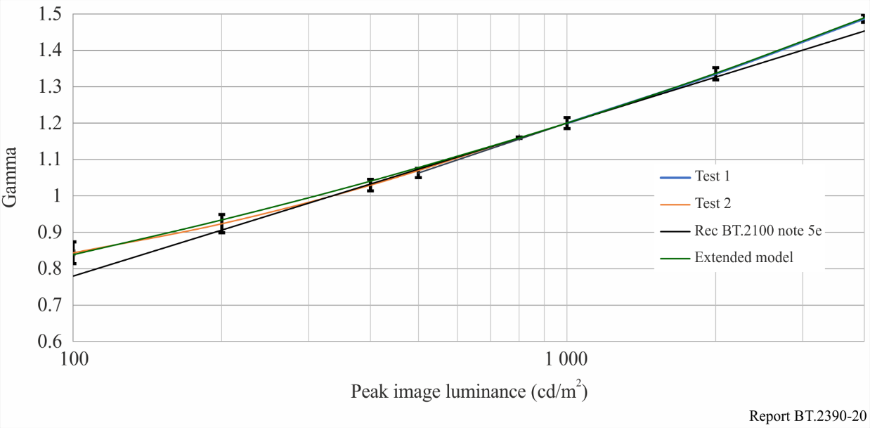
FIGURE 20 — Gamma value to match images for different screen peak brightness
图 20. 为不同屏幕峰值亮度匹配图像所需的伽马值。
Bringing together the results of all studies, it is found that the appropriate system gamma (γ) for different brightness displays, in the reference environment, can be determined using the following equation:
综合所有研究的结果可知,在参考环境中,不同亮度显示设备的合适系统伽马(γ)可用下式确定:
where:
LW: nominal peak luminance of the display in cd/m2.
式中:
- L_W:显示设备的标称峰值亮度,单位 cd/m²。
According to the subjective tests conducted by the BBC, displays for a range of different values of nominal peak luminance, specifically the range from 400 cd/m2 to 2 000 cd/m2, can be shown to provide a consistent look by varying the value of gamma in the HLG OOTF in accordance with the equation above. This allows programmes to be made using displays with different peak luminance. Outside this range of peak luminance, the match of this simple model to the experimental detail starts to deteriorate. An extended model, described in [14] and also illustrated in Fig. 20, is given by:
根据 BBC 所做的主观测试,对一系列不同标称峰值亮度(具体为 400 cd/m² 至 2 000 cd/m² 范围)的显示设备,只要按上式改变 HLG OOTF 中的伽马值,就能呈现一致的观感。这使得节目可以用不同峰值亮度的显示设备来制作。超出这一峰值亮度范围后,这个简单模型与实验细节的吻合度开始变差。文献 [14] 描述了一个扩展模型(也示于图 20),其表达式为:
where:
式中:
This may be used for displays with peak luminance outside the range above. Within that range the two models are virtually identical and will provide equally good performance.
该模型可用于峰值亮度超出上述范围的显示设备。在该范围之内,两个模型几乎完全相同,表现同样良好。
It should be noted that using a gamma adjustment to adapt to different peak luminances has its limitations. Television receivers typically apply different and more sophisticated methods. The acceptability of displays with different peak luminance values is a decision for individual producers and might differ between productions.
需要指出,靠调整伽马来适应不同峰值亮度的做法有其局限。电视接收机通常采用与之不同、更为复杂的方法。不同峰值亮度的显示设备是否可接受,由各制作方自行决定,且可能因节目而异。
Many television programmes are produced in environments that differ considerably from the reference viewing environment. The luminance of the surround may be considerably higher than the recommended 5 cd/m2.
许多电视节目是在与参考观看环境差别很大的环境中制作的,周边亮度可能远高于建议的 5 cd/m²。
Recommendation ITU-R BT.2100 recognises that the HLG display gamma may need to be reduced in brighter viewing environments, to compensate for the differences in the adaptation state of the eye. The BBC conducted subjective tests to measure the change in gamma necessary to perceptually match images displayed across a range of peak luminances in the reference and in non-reference environments. Twenty-one viewers participated in the tests. The results, from 21 viewers, that show the reduction in gamma as the surround brightness increases are presented below in Fig. 21.
建议书 ITU-R BT.2100 认识到,在较亮的观看环境中可能需要调低 HLG 显示伽马,以补偿眼睛适应状态的差异。BBC 做了主观测试,测量在参考环境与非参考环境中、为使一系列峰值亮度下显示的图像在感知上相匹配所需的伽马变化。21 名观众参加了测试。这 21 名观众的结果表明,周边亮度升高时伽马随之降低,见下方图 21。
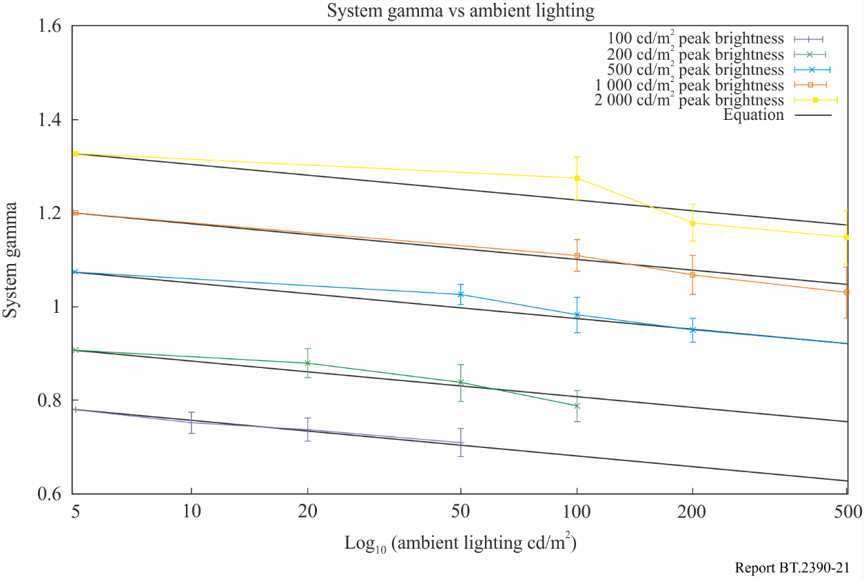
FIGURE 21 — Graph of system gamma vs. ambient lighting for a number of different screen luminances, with lines of best fit
图 21. 若干不同屏幕亮度下系统伽马随环境照明变化的曲线图,附最佳拟合直线。
The line of best fit, which provides an indication of how gamma should be adjusted in non-reference environments, is given by the equation below:
最佳拟合直线给出了非参考环境中伽马应如何调整的参考依据,其表达式如下:
where:
γbright: system gamma for display surrounds greater than 5 cd/m2
γref: system gamma for reference environment, calculated according to Recommendation ITU-R BT.2100 Note 5f (and above)
Lamb: ambient luminance level in cd/m2.
式中:
- γ_bright:显示周边大于 5 cd/m² 时的系统伽马;
- γ_ref:参考环境下的系统伽马,按建议书 ITU-R BT.2100 注 5f(及上文)计算;
- L_amb:环境光亮度电平,单位 cd/m²。
By adjusting the display gamma to compensate for non-reference viewing environments in this way more consistent results may be achieved in a wide range of production environments.
以这种方式调整显示伽马来补偿非参考观看环境,便能在各种各样的制作环境中获得更一致的结果。
An alternative model is described in [14] which matches the form of the extended model for the variation of gamma with peak display luminance (LW) and which also includes the variation of gamma with surround luminance:
文献 [14] 描述了另一个模型,它与伽马随显示峰值亮度(L_W)变化的扩展模型形式一致,同时还纳入了伽马随周边亮度的变化:
where μ = 0.98, κ = 1.111, Lsurround is the surround luminance in cd/m2, and the reference surround luminance Lsurround ref is 5 cd/m2.
式中 μ = 0.98,κ = 1.111,L_surround 为周边亮度(单位 cd/m²),参考周边亮度 L_surround ref 为 5 cd/m²。
6.3 The hybrid log-gamma electro-optical transfer function (EOTF)
6.3 混合对数伽马电光转换函数(EOTF)
In order to specify the complete television system an EOTF is needed, as well as the OETF defined in § 6.1. The HLG EOTF maps the HLG signal representing the scene to the light emitted from the display.
要完整规定整个电视系统,除 6.1 节定义的 OETF 外,还需要一个 EOTF。HLG EOTF 把代表场景的 HLG 信号映射为显示设备所发出的光。
The EOTF mapping should:
- preserve the artistic intent of the programme maker (and provide a suitable rendering intent),
- allow for the dynamic range of the display from black level to peak white, and
- minimize quantization artefacts.
EOTF 映射应当:
- 保留节目制作者的艺术意图(并提供合适的渲染意图);
- 兼顾显示设备从黑位到峰值白的动态范围;
- 尽量减少量化伪影。
The EOTF defined in Table 5 of Recommendation ITU-R BT.2100 and described below is similar to the conventional display gamma curve, thereby maximizing backward compatibility, whilst also meeting the three preceding requirements.
建议书 ITU-R BT.2100 表 5 所定义、下文所述的 EOTF,与常规显示伽马曲线相似,从而在满足上述三项要求的同时,使向后兼容性达到最大。
where:
FD: luminance of a displayed linear component {RD, GD, or BD}, in cd/m2
E´: non-linear signal {R′, G′, B′} as defined for the OETF.
式中:
- F_D:显示出的某个线性分量 {R_D、G_D 或 B_D} 的亮度,单位 cd/m²;
- E′:非线性信号 {R′, G′, B′},定义同 OETF。
The inverse OETF, OETF-1, is given by:
逆 OETF(OETF⁻¹)为:
and β, the black level lift, is given by:
而黑位抬升 β 为:
where:
LW: nominal peak luminance of the display in cd/m2 for achromatic pixels
LB: display luminance for black in cd/m2.
式中:
- L_W:无彩色像素的显示标称峰值亮度,单位 cd/m²;
- L_B:黑的显示亮度,单位 cd/m²。
The black level lift, conventionally known as the “brightness” adjustment in CRT displays, adapts the EOTF to the minimum luminance that can be seen in the actual, not necessarily reference, viewing conditions. The appropriate value for β may be determined in any particular circumstance by using the PLUGE test signal specified in Recommendation ITU-R BT.814.
黑位抬升在 CRT 显示设备中通常称为“亮度(brightness)”调整,它使 EOTF 适应实际(未必是参考)观看条件下可见的最低亮度。在任何具体情形下,都可用建议书 ITU-R BT.814 规定的 PLUGE 测试信号来确定 β 的合适取值。
6.4 Compatibility with SDR displays
6.4 与 SDR 显示设备的兼容性
Both PQ and HLG provide limited compatibility when directly connected to legacy SDR displays with BT.709 colorimetry. In the absence of additional processing HLG has a degree of compatibility when shown on SDR UHDTV displays that have been designed to accept signals in the BT.2020 colour space.
PQ 与 HLG 在直接连接采用 BT.709 色度学的传统 SDR 显示设备时,兼容性都有限。在不作额外处理的情况下,HLG 显示在为接收 BT.2020 色彩空间信号而设计的 SDR UHDTV 显示设备上时,具有一定程度的兼容性。
Concerning the degree of compatibility achieved by HLG, hue changes can be perceptible on the SDR display should images contain bright areas of highly saturated colour or very high code values. Generally, such high code values would be used for specular highlights and thus constitute a small proportion of the picture. The acceptability of the degree of compatibility of HLG might be a commercial decision by specific broadcasters or for a specific application.
就 HLG 所能达到的兼容程度而言,如果图像含有高饱和色彩的明亮区域或非常高的码值,SDR 显示设备上可能察觉到色相变化。一般来说,这样高的码值会用于镜面高光,因而只占画面的一小部分。HLG 的兼容程度是否可接受,可能是特定广播机构或特定应用的商业决策。
When PQ or HLG HDR signals are converted for use in SDR ITU-R BT.709 facilities, the conversion process is expected to perform the colour space, HDR to SDR and any video format conversion in such a way as to minimise perceptible changes in colour for all types of HDR content, regardless of the code value ranges in use.
当 PQ 或 HLG HDR 信号被转换以用于 SDR ITU-R BT.709 设施时,转换过程应在完成色彩空间转换、HDR 到 SDR 转换以及任何视频格式转换时,做到对各类 HDR 内容都尽量减少可察觉的色彩变化,而不论所用码值范围如何。
6.5 Traditional colour reproduction for camera signals
6.5 相机信号的传统色彩还原
The HLG OOTF (system gamma applied on luminance) uses scene-referred camera signals that result in a display that closely preserves the chromaticity of the scene as imaged by the camera. This differs from the traditional colour reproduction provided by the HDTV and UHDTV OOTFs, which produce more saturated colours which viewers of existing SDR content have become familiar with. Should such a traditional colour reproduction be desired, a gamma of 1.2 could be applied on the RGB components of a camera signal to produce more saturated colours. This approach is illustrated in Fig. 22.
HLG OOTF(把系统伽马施加于亮度)使用场景参考的相机信号,使显示结果较好地保留了相机所成场景的色品。这与 HDTV 和 UHDTV 的 OOTF 所提供的传统色彩还原不同:后者产生更饱和的色彩,而现有 SDR 内容的观众已对这种色彩习以为常。若希望得到这种传统色彩还原,可对相机信号的 RGB 分量施加 1.2 的伽马以产生更饱和的色彩。这一做法示于图 22。
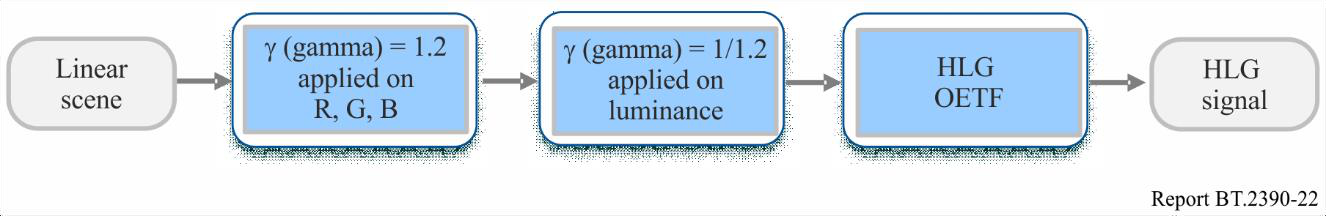
FIGURE 22 — Block diagram of signal chain to produce more saturated colours
图 22. 用于产生更饱和色彩的信号链框图。
In this Figure (linear) light from the camera is first processed by applying a gamma curve (γ = 1.2) independently to the red, green and blue colour components. Applying gamma separately to red, green and blue components does two things. Firstly, it adjusts the overall tone curve. Secondly, because it is applied separately to the colour components, the colour saturation is increased. The second processing block undoes the modification of the tone curve by applying an inverse gamma (γ = 1/1.2) to the luminance component of the signal. Applying gamma to the luminance component only (as in the HLG OOTF) leaves the ratio of the red to green to blue components unchanged and, hence, does not change the saturation.
在该图中,来自相机的(线性)光首先经第一步处理:对红、绿、蓝三个颜色分量分别施加一条伽马曲线(γ = 1.2)。对红、绿、蓝分量分别施加伽马会做两件事:其一,调整总体色调曲线;其二,由于是分别施加于各颜色分量,色彩饱和度因而提高。第二个处理模块通过对信号的亮度分量施加逆伽马(γ = 1/1.2),撤销对色调曲线的改动。只对亮度分量施加伽马(如 HLG OOTF 那样),会使红、绿、蓝分量之比保持不变,因而不改变饱和度。
Overall, the effect of applying such processing is to increase colour saturation whilst leaving the overall tone curve unchanged. Conversely, it would be possible to use similar processing to modify a signal representing the traditional look to instead more closely represent the chromaticity of the scene as imaged by the camera.
总体而言,施加这种处理的效果是:在不改变总体色调曲线的前提下提高色彩饱和度。反过来,也可用类似的处理来改造一个代表传统观感的信号,使其转而更贴近相机所成场景的色品。
7 Colour representation for chroma sub-sampling
7 用于色度子采样的色彩表示
The legacy Y′C′BC′R non-constant luminance format is a colour-opponent based encoding scheme (in which signals are interpreted based on colour differences in an opposing manner) intended to separate luma from chroma information for the purposes of chroma subsampling (i.e. 4:2:2 and 4:2:0). High dynamic range and wide colour gamut content reveal the limitations of existing colour encoding methods. Errors that were previously small with standard dynamic range can become magnified. Recommendation ITU-R BT.2020 provides an alternative to Y′C′BC′R, i.e. the Y′CC′BCC′RC constant luminance format. This format resolves the issue of chroma leakage into the Y′ signal but does not solve the problem of luminance contamination of the C′BC and C′RC components. Recommendation ITU-R BT.2100 provides an alternative method for colour difference encoding called constant intensity, which is based on IPT colour space [15] developed by Ebner and Fairchild.
传统的 Y′C′BC′R 非恒定亮度格式是一种基于颜色对立的编码方案(即以拮抗方式按色差来解读信号),目的是把亮度信号(luma)与色度信号(chroma)分离,以便进行色度子采样(即 4∶2∶2 和 4∶2∶0)。高动态范围与宽色域内容暴露了现有色彩编码方法的局限:以往在标准动态范围下很小的误差,可能被放大。建议书 ITU-R BT.2020 给出了 Y′C′BC′R 的一种替代方案,即 Y′CC′BCC′RC 恒定亮度格式。该格式解决了色度信号渗入 Y′ 信号的问题,但并未解决亮度污染 C′BC 和 C′RC 分量的问题。建议书 ITU-R BT.2100 提供了另一种色差编码方法,称为恒定强度,它以 Ebner 与 Fairchild 提出的 IPT 色彩空间 [15] 为基础。
7.1 Non-constant luminance (NCL) Y′C′BC′R
7.1 非恒定亮度(NCL)Y′C′BC′R
Y′C′BC′R is widely used for standard dynamic range content and requires a specific conversion based on the primaries being encoded and decoded. Recommendation ITU-R BT.2100 specifies PQ as a non-linearity to be used with the BT.2020 colour primaries. While Y′C′BC′R performs satisfactorily in many cases, some limitations have emerged for its use in high dynamic range wide colour gamut scenarios.
Y′C′BC′R 广泛用于标准动态范围内容,它需要根据所编码和解码的基色作特定的转换。建议书 ITU-R BT.2100 规定 PQ 作为与 BT.2020 基色配合使用的非线性变换。Y′C′BC′R 在许多情形下表现令人满意,但在高动态范围、宽色域场景中使用时已显露出一些局限。
Limitations of Y′C′BC′R with wide colour gamut and high dynamic range
– Quantization distortions due to bit depth limitations with the increased colour volume.
– Chroma subsampling distortions due to a perceptually uneven distribution of code words.
– Colour volume mapping distortions due to incorrectly predicted hue and luminance.
– Error propagation from chroma to luma channels.
Y′C′BC′R 在宽色域与高动态范围下的局限:
- 因色彩体积增大、位深受限而产生的量化失真;
- 因码字在感知上分布不均而产生的色度子采样失真;
- 因色相和亮度预测不准而产生的色彩体积映射失真;
- 误差从色度通道传播到亮度信号通道。
The constant luminance method specified in Recommendation ITU-R BT.2020 helps reduce the last of these, but this solution is not being widely adopted because the benefits are considered modest and entail some additional complexity.
建议书 ITU-R BT.2020 规定的恒定亮度方法有助于减轻其中最后一项,但这一方案并未被广泛采用,因为人们认为其收益有限,还会带来一些额外的复杂度。
7.2 Constant intensity ICTCP encoding
7.2 恒定强度 ICTCP 编码
An alternative to constant luminance (CL) Y′CC′BCC′RC is the constant intensity (CI) ICTCP colour representation. Like Y′C′BC′R, ICTCP is a colour-opponent based encoding scheme intended to separate luma from chroma information. CI offers the same benefit as CL in that the chroma channels are lacking luminance, but ICTCP has the advantage that the lines of constant hue are straighter, and the MacAdam’s ellipses are more circular. The CI neutral (grey) axis is encoded with the PQ or HLG non-linearity to match the human visual system, and to optimize it for high dynamic range signal encoding. The alternative 3x3 colour matrices used to generate the colour difference channels have been optimized [16] for the human visual system perception of HDR and WCG. The in-camera encoding and in-display decoding steps for ICTCP are identical to those for NCL Y′C′BC′R, so ICTCP is compatible with that hardware.
恒定亮度(CL)Y′CC′BCC′RC 的一种替代是恒定强度(CI)ICTCP 色彩表示。与 Y′C′BC′R 一样,ICTCP 也是基于颜色对立的编码方案,目的是把亮度信号与色度信号分离。CI 具有与 CL 相同的好处——色度通道不含亮度;但 ICTCP 还另有优势:等色相线更直,麦克亚当椭圆更接近圆形。CI 的中性(灰)轴用 PQ 或 HLG 非线性编码,以契合人眼视觉系统,并针对高动态范围信号编码作优化。用于生成色差通道的替代 3×3 色彩矩阵,已针对人眼视觉系统对 HDR 和广色域(WCG)的感知作了优化 [16]。ICTCP 在相机内的编码和在显示设备内的解码步骤,与 NCL Y′C′BC′R 完全相同,因此 ICTCP 与该类硬件兼容。
7.2.1 Constant intensity ICTCP encoding
7.2.1 恒定强度 ICTCP 编码
Below are the conversion steps needed to get from camera linear RGB sensor signals into Y′C′BC′R and into ICTCP [17]. Note that the matrix coefficients are decimal values that differ very slightly from the values shown in Recommendation ITU-R BT.2100; the values shown in the Recommendation should be used in actual implementations.
下面给出从相机线性 RGB 传感器信号转换到 Y′C′BC′R 以及 ICTCP 所需的步骤 [17]。需要注意,这里的矩阵系数为十进制数值,与建议书 ITU-R BT.2100 所列数值略有差异;实际实现时应采用该建议书中给出的数值。
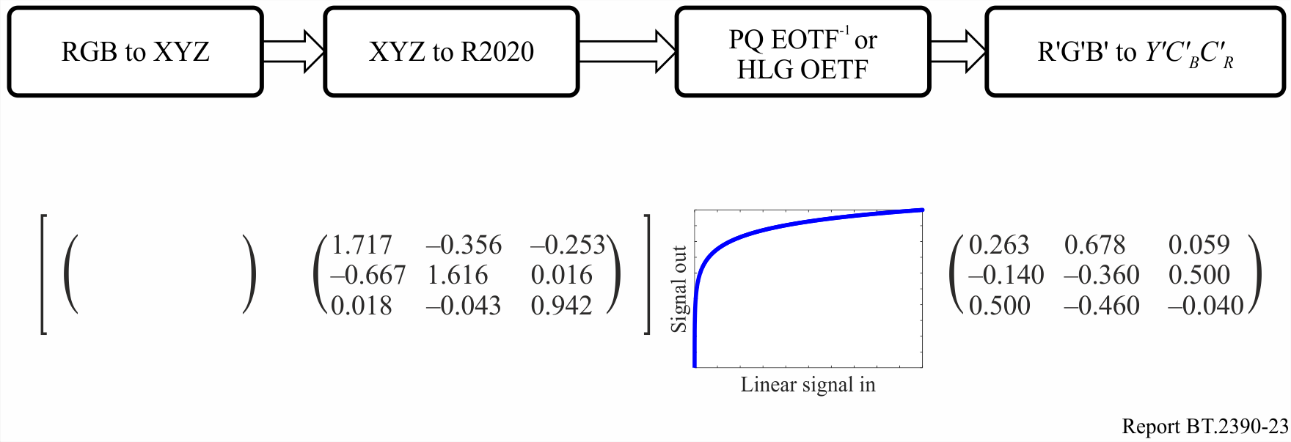
FIGURE 23 — Camera RGB conversion To Y′C′BC′R
图 23. 相机 RGB 转换为 Y′C′BC′R。
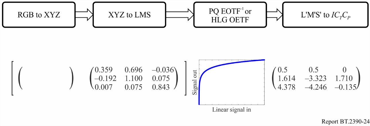
FIGURE 24 — Camera RGB conversion to ICTCP
图 24. 相机 RGB 转换为 ICTCP。
7.2.2 Advantages of constant intensity ICTCP
7.2.2 恒定强度 ICTCP 的优势
The specific design of the constant intensity colour space provides several benefits versus the Non-Constant Luminance colour space when used with the PQ or HLG non-linearity to provide HDR.
与非恒定亮度色彩空间相比,恒定强度色彩空间的专门设计在配合 PQ 或 HLG 非线性提供 HDR 时,带来若干好处。
Achromatic channel: The achromatic axis of Y′C′BC′R (Y′ encoded in PQ or HLG) does not fully decorrelate luminance from colour. Therefore distortions introduced into the chroma channels can propagate to luminance where they become much more noticeable. As shown in Fig. 25, the achromatic axis of ICTCP (I) corresponds very closely with luminance (where luminance is a weighted sum of linear R,G,B). This is an indicator of how well ICTCP separates luma from chroma information. This reduces errors that can be introduced when spatially sub-sampling the chroma components compared to conventional non-constant luminance encoding. The axes in Fig. 25 are from zero to full scale in PQ space. (The luminance errors shown for Y′C′BC′R are not as large for legacy systems using standard dynamic range with gamma encoding.)
无彩色通道:Y′C′BC′R 的无彩色轴(以 PQ 或 HLG 编码的 Y′)并未把亮度与色彩完全去相关。因此,引入色度通道的失真可能传播到亮度,在那里变得明显得多。如图 25 所示,ICTCP 的无彩色轴(I)与亮度(亮度为线性 R、G、B 的加权和)高度对应。这是衡量 ICTCP 把亮度信号与色度信号分离程度的一项指标。与常规非恒定亮度编码相比,这减少了对色度分量作空间子采样时可能引入的误差。图 25 的坐标轴在 PQ 空间中从零到满量程。(对采用标准动态范围、伽马编码的传统系统而言,Y′C′BC′R 所示的亮度误差并没有这么大。)
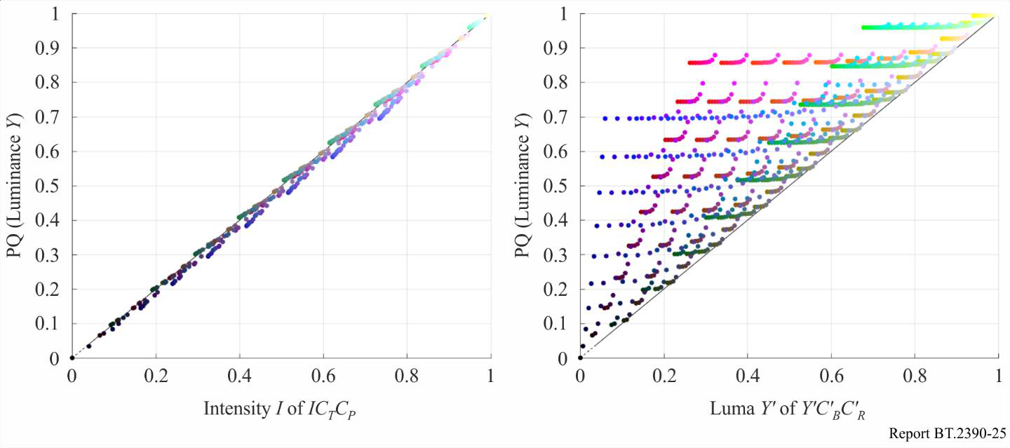
FIGURE 25 — Luminance correlation
图 25. 亮度相关性。
Quantization to limited bit-depth: Figure 26 shows the worst case visual colour difference between chroma channel code values (using ∆E2000) at various luminance levels. 10-bit ICTCP provides an approximately 1.5-bit colour difference improvement over 10-bit Y′C′BC′R. At less than an average of 1.0 ∆E above the visual difference threshold, use of ICTCP significantly decreases visible distortions thus enabling excellent colour performance with 10-bit encoding.
量化到有限位深:图 26 给出在各亮度电平下、色度通道码值之间最坏情况的视觉色差(以 ΔE2000 衡量)。10 比特 ICTCP 相比 10 比特 Y′C′BC′R,色差改善约 1.5 比特。其色差平均不到视觉差异阈值之上 1.0 ΔE,因此采用 ICTCP 可显著减少可见失真,使 10 比特编码也能获得出色的色彩表现。
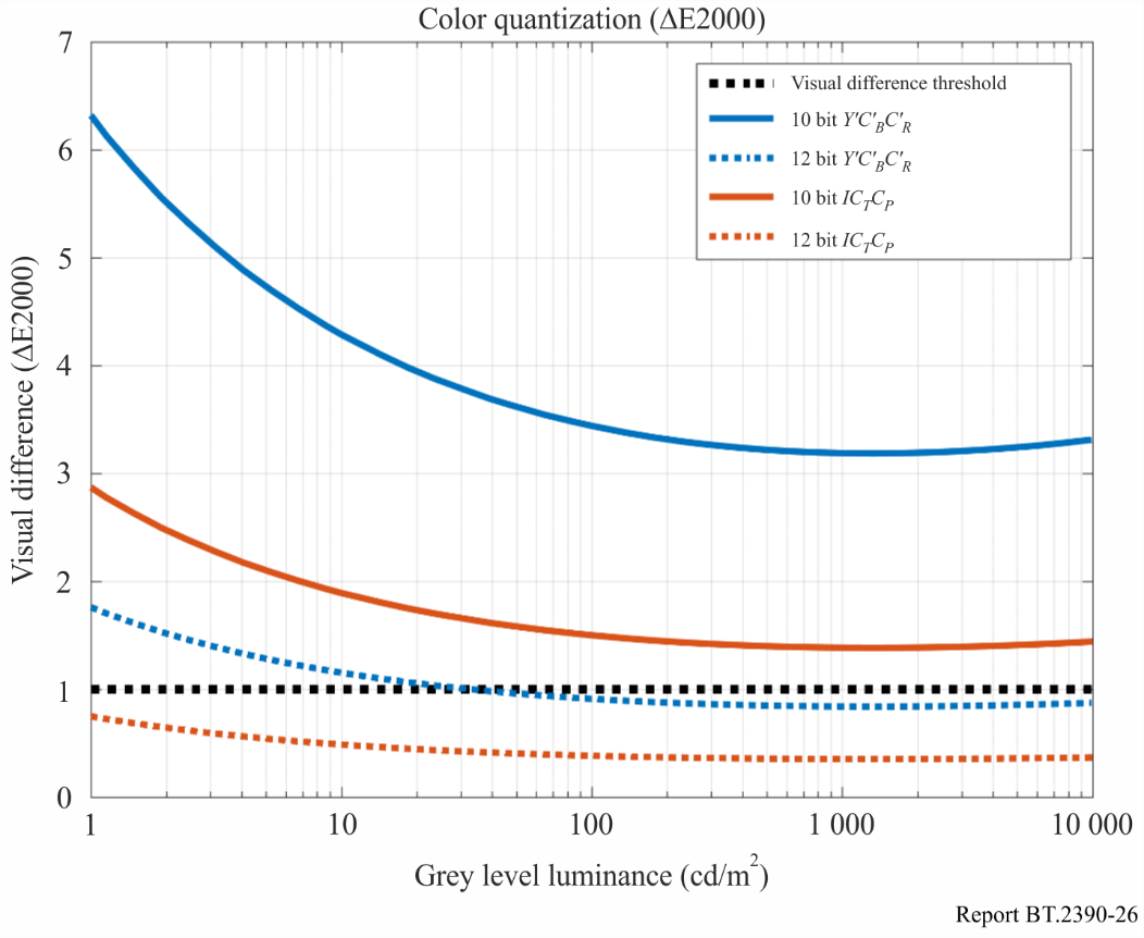
FIGURE 26 — Maximum colour deviation at various bit-depths
图 26. 各位深下的最大色彩偏差。
Uniformity and hue linearity: A colour space is hue linear when the hue remains constant as saturation or intensity are changed. Hue linearity is important during any interpolation such as colour volume mapping, chroma subsampling, and blending/fading. Y′C′BC′R has large deviations (see Fig. 27) that cause hue shifts with highly saturated colours. ICTCP was designed to minimize deviation from lines of constant hue thereby reducing hue shifts. In addition, ICTCP has a more uniform distribution of colours. This improves efficiency, reduces worst case quantization and interpolation errors. If the CL format specified in Recommendation ITU-R BT.2020 is applied to HDR, the Y′CC′BCC′RC representation introduces additional (over NCL) errors in skin tones. The blue is significantly improved versus NCL (but still contains errors) and CL has significantly worse errors in the red and green regions (see Fig. 28). (The BT.2020 CL coefficients were designed for use with the SDR camera characteristic, and thus were not optimized for use in HDR.)
均匀性与色相线性:当饱和度或强度变化而色相保持不变时,色彩空间即为色相线性。在色彩体积映射、色度子采样、混合/淡变等任何插值过程中,色相线性都很重要。Y′C′BC′R 存在很大的偏差(见图 27),会使高饱和色彩发生色相偏移。ICTCP 在设计上力求使偏离等色相线的程度最小,从而减少色相偏移。此外,ICTCP 的色彩分布更均匀,这提高了效率,减小了最坏情况下的量化和插值误差。若把建议书 ITU-R BT.2020 规定的 CL 格式用于 HDR,Y′CC′BCC′RC 表示会在肤色上引入(相对 NCL 而言)额外的误差。蓝色相比 NCL 有明显改善(但仍含误差),而 CL 在红色和绿色区域的误差则明显更大(见图 28)。(BT.2020 的 CL 系数是为配合 SDR 相机特性而设计的,因此并未针对 HDR 作优化。)
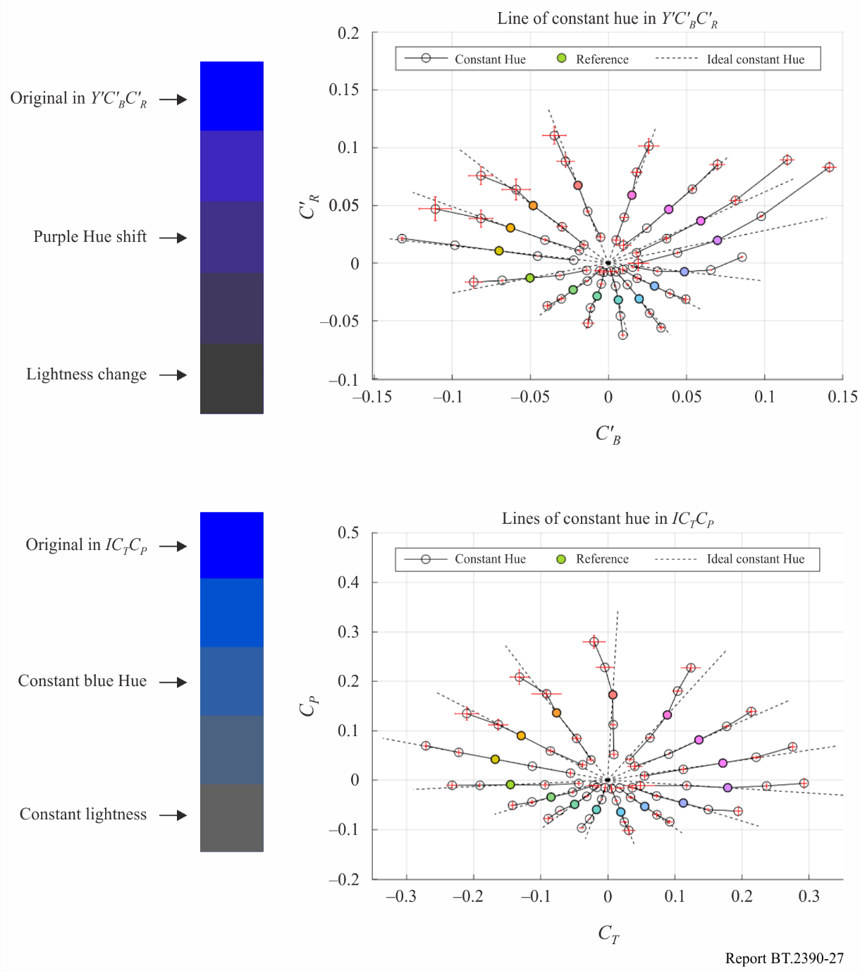
FIGURE 27 — Blue hue linearity comparison (using PQ)
图 27. 蓝色色相线性对比(使用 PQ)。
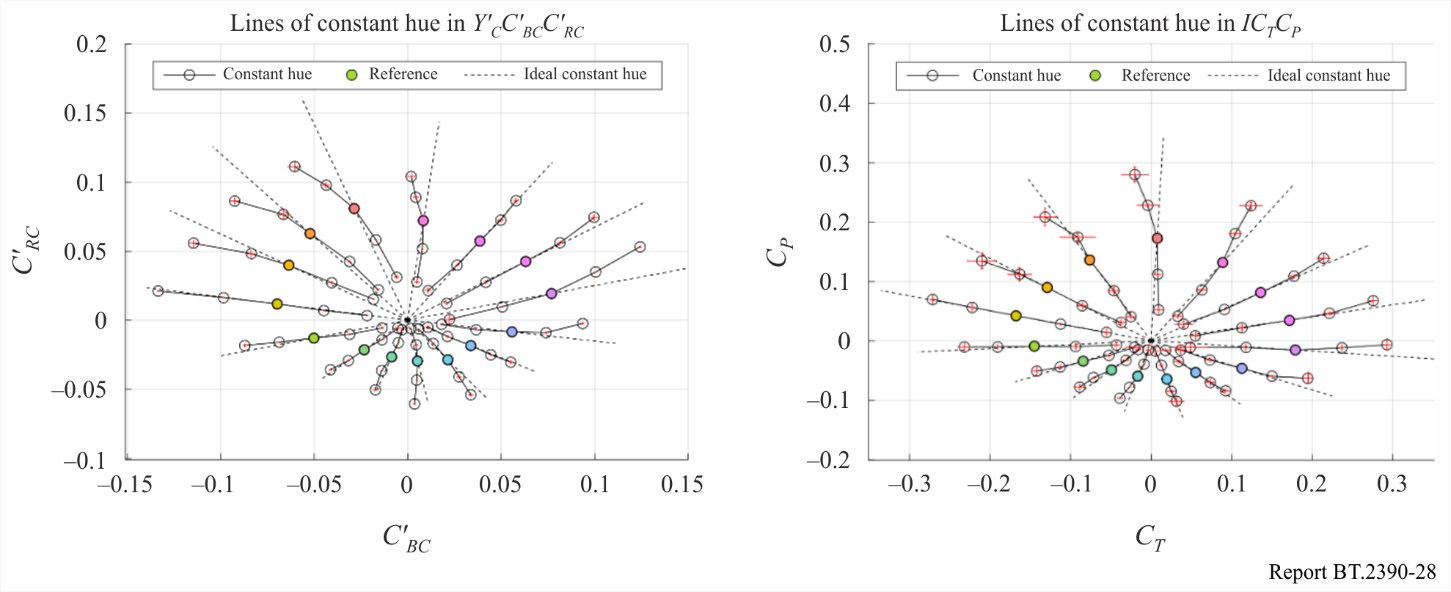
FIGURE 28 — Constant luminance vs. constant intensity hue linearity comparison (PQ)
图 28. 恒定亮度与恒定强度的色相线性对比(PQ)。
Colour sub-sampling: Figure 29 shows a practical example of a colour sub-sampling distortion due to NCL encoding. Two very similar colours with a ∆E2000 of 0.1 were sub-sampled to 10-bit 4:2:0 in Y′C′BC′R and ICTCP and reconstructed. Due to the poor decorrelation between Y′ of Y′C′BC′R and luminance (Y), errors introduced in chroma during sub-sampling spread to the luminance and became more visible with a ∆E2000 of 4.0. Constant intensity ICTCP has a higher tolerance for chroma error and the colours remain indistinguishable with a ∆E2000 of 0.2.
色彩子采样:图 29 给出一个因 NCL 编码而产生色彩子采样失真的实例。把两种 ΔE2000 仅为 0.1 的极相近色彩,分别在 Y′C′BC′R 和 ICTCP 中子采样为 10 比特 4∶2∶0 再重建。由于 Y′C′BC′R 的 Y′ 与亮度(Y)去相关较差,子采样时引入色度的误差扩散到亮度,变得更明显,ΔE2000 达到 4.0。恒定强度 ICTCP 对色度误差的容忍度更高,色彩仍难以分辨,ΔE2000 仅为 0.2。
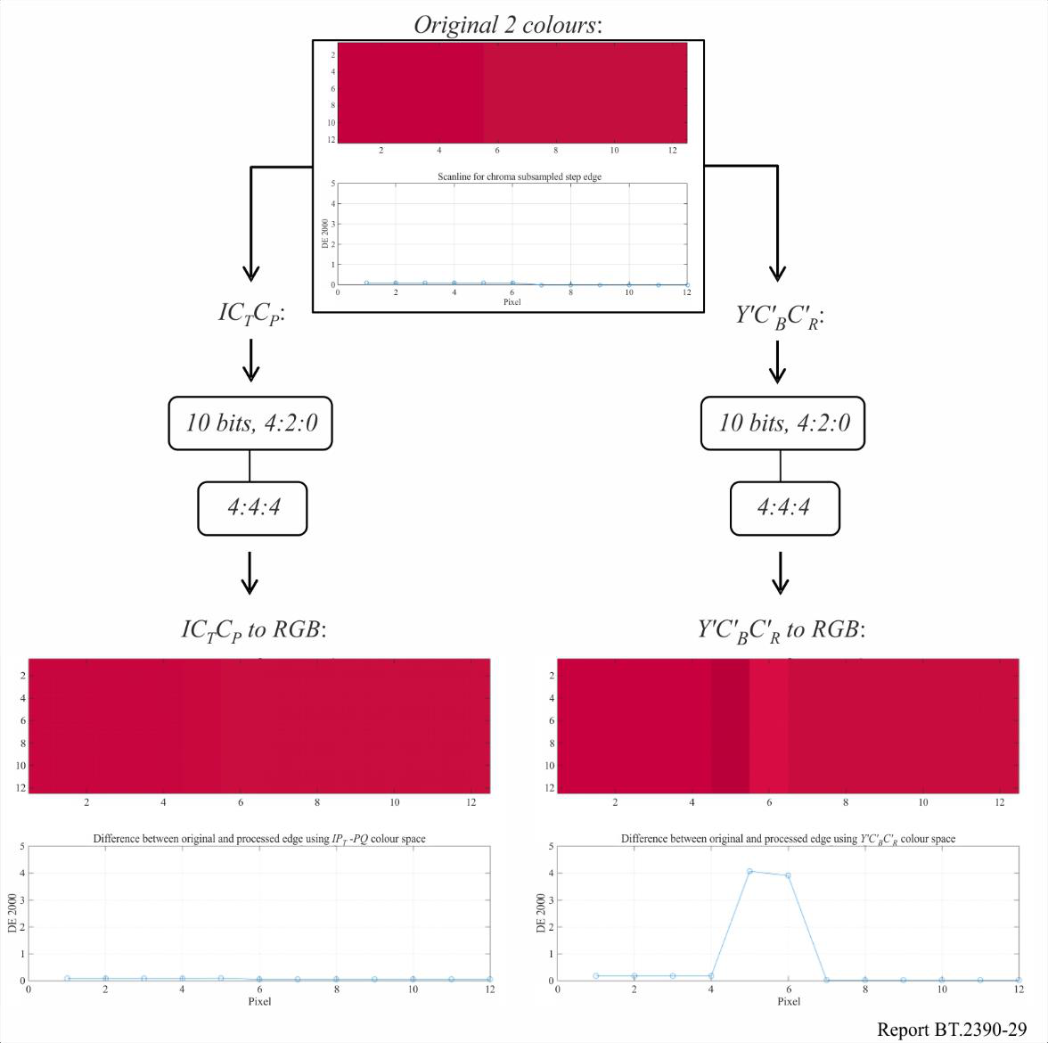
FIGURE 29 — Colour sub-sampling distortions based on correlation with luminance
图 29. 基于与亮度相关性的色彩子采样失真。
参考文献
[1] L.B. Wolf. Relative brightness of specular and diffuse reflection. Optical Engineering, 33(1), pp. 285-293, Jan 1994.
[2] V. Interrante, H. Fuchs, and S. Pizer (1997), Conveying the 3D shape of transparent surfaces via texture. ICASE report No 97-27. NASA contractor report 201705.
[3] R. Dror, A. Willsky, and E.H. Adelson (2004), Statistical characterization of real world illumination. JOV 4, pp. 821-837.
[4] A. Blake and H. Bulthoff (1991), Shape from specularities: computation and psychophysics. Phil Trans from the Royal Society of London. Series B, 33, pp. 237-252.
[5] S. Hecht, C. Haig, A.M. Chase, The influence of light adaptation on subsequent dark adaptation of the eye, Journal of General Physiology, 20 (1937), pp. 831-850.
[6] M.G.M. Stokkermans and I. Heynderickx (2014), Temporal dark adaptation to spatially complex backgrounds: effect of an additional light source. JOSA A V31 #7, pp. 1485-1494.
[7] R. Mantiuk, S. Daly, and L. Kerofsky (2010), “The luminance of pure black: exploring the effect of surround” SPIE Electronic Imaging Conference, San Jose.
[8] Rempel, A., Heidrich, W., Li, H., and Mantiuk, R., Video viewing preferences for HDR displays under varying ambient illumination, [Proc. of the 6th Symposium on Applied Perception in Graphics and Visualization], 45-52, ACM (2009).
[9] S. Daly, T. Kunkel, X. Sun, S. Farrell, and P. Crum (2013), “Viewer Preferences for Shadow, Diffuse, Specular, and Emissive Luminance Limits of High Dynamic Range Displays”, SID Display Week, paper 41.1, Vancouver, Canada.
[10] R. De Valois and K. De Valois (1990), Spatial Vision, p. 26, Ch. 2, Oxford Science Publications, Oxford University press.
[11] N. Salvaggio (2008), Basic photographic materials and processes, 3rd edition. Focal press.
[12] S. Miller, M. Nezamabadi, S. Daly, “Perceptual Signal Coding for More Efficient Usage of Bit Codes,” SMPTE Mot. Imag. J., 122(4):52-59, May-June 2013.
[13] T. Borer, A. Cotton, M. Pindoria and S. Thompson, “Approaches to high dynamic range video”, 2016 Digital Media Industry & Academic Forum (DMIAF), Santorini, 2016, pp. 71-76. doi: 10.1109/DMIAF.2016.7574905.
[14] T. Borer, “Display of high dynamic range images under varying viewing conditions”, Proc. SPIE 10396, Applications of Digital Image Processing XL, 103960H (19 September 2017); doi: 10.1117/12.2274253; http://dx.doi.org/10.1117/12.2274253.
[15] F. Ebner, M. Fairchild, “Derivation and Modelling of Hue Uniformity”. Rochester Institute of Technology. July 1998.
[16] “Encoding Color Difference Signals for High Dynamic Range and Wide Gamut Imagery”, Froehlich et al., Color and Imaging Conference, Volume 2015, Number 1, October 2015, pp. 240-247(8).
[17] J. Pytlarz, R. Atkins, T. Lu, F. Pu, P. Yin, T. Chen, W. Husak, “Overview of IPT-PQ Color Space”, Doc. m37266, October 2015, Geneva, Switzerland.
术语表
Following is a list of terms within Report ITU-R BT.2390 which may not have been encountered by the reader in the context of High Dynamic Range.
以下列出报告 ITU-R BT.2390 中读者在高动态范围背景下可能不太熟悉的若干术语。
Camera RAW output: image data produced by, or internal to, a digital camera that has not been processed, except for A/D conversion and the following optional steps: linearization, dark current/frame subtraction, shading and sensitivity (flat field) correction, flare removal, white balancing (e.g. so the adopted white produces equal RGB values or no chrominance), missing colour pixel reconstruction (without colour transformations).
相机 RAW 输出(Camera RAW output): 由数字相机产生或在其内部生成、未经处理的图像数据,但以下步骤除外:模数(A/D)转换,以及如下若干可选步骤——线性化、暗电流/暗场扣除、阴影与灵敏度(平场)校正、去除杂散光、白平衡(如使所采用的白产生相等的 RGB 值或不含色度信息)、缺失颜色像素的重建(不含色彩变换)。
Chroma: a term specifying that a signal represents one of the non-linear two-colour difference signals related to the primary colours. The symbols used for chroma signals are denoted as C′B and C′R.
NOTE – The term chroma is used rather than the term chrominance in order to avoid the implication of the use of linear light transfer characteristics that is often associated with the term chrominance. However, in many of the ITU-R Recommendations on television systems the term ‘colour-difference signals’ is used rather than “chroma” for C′B and C′R.
色度信号(Chroma): 表示信号代表与基色相关的两个非线性色差信号之一。色度信号的符号记为 C′B 和 C′R。
注——之所以用 chroma 而非 chrominance(色度信息),是为了避免后者常带有的“采用线性光传输特性”之含义。不过,在许多关于电视系统的 ITU-R 建议书中,C′B 和 C′R 用的是“色差信号”一词,而非“chroma”。
Chroma leakage: crosstalk inherent in the Y′C′BC′R non-constant luminance format from the chroma signals into the displayed luminance level and which can result in small errors in the luminance near signal transitions in highly saturated areas caused by chroma signal subsampling.
色度渗漏(Chroma leakage): Y′C′BC′R 非恒定亮度格式所固有的串扰,即色度信号串入显示亮度电平;在高饱和区域,因色度信号子采样,可能在信号跳变附近造成亮度上的微小误差。
Colour emissive highlights: typically small areas of bright coloured light.
彩色自发光高光(Colour emissive highlights): 通常是面积很小的明亮彩色光区。
HDR floating point format: linear R, G, B signals each encoded in 16-bit floating point per IEEE standard 754-2008, as defined in Recommendation ITU-R BT.2100.
HDR 浮点格式(HDR floating point format): 线性 R、G、B 信号,各自按 IEEE 754-2008 标准以 16 比特浮点编码,定义见建议书 ITU-R BT.2100。
Luma: a term specifying that a signal represents the monochrome information related to non-linear colour signals. The symbol for luma information is denoted as Y′.
NOTE – The term luma is used rather than the term luminance in order to signify the use of non-linear light transfer characteristics as opposed to the linear characteristics in the term luminance. However, in many of the ITU-R Recommendations on television systems, the term ‘luminance signal’ is used rather than ‘luma’ for Y′ together with C′B and C′R.
亮度信号(Luma): 表示信号代表与非线性颜色信号相关的单色信息。亮度信号信息的符号记为 Y′。
注——之所以用 luma 而非 luminance(亮度),是为了表明采用的是非线性光传输特性,以区别于 luminance 所含的线性特性。不过,在许多关于电视系统的 ITU-R 建议书中,与 C′B、C′R 并列的 Y′ 用的是“亮度信号(luminance signal)”一词,而非“luma”。
Luminance: the photometrically weighted flow of light per unit area travelling in a given direction. It describes the amount of light that passes through, is emitted from, or is reflected from a particular area, and falls within a given solid angle. It is expressed in candelas per square metre (cd/m2).
NOTE – The relative luminance of a pixel can be approximated by a weighted sum of the linear colour components; the weights depend on the colour primaries and the white point.
亮度(Luminance): 沿给定方向、经光度学加权的单位面积光通量。它描述通过、发自或反射自某一特定面积、并落入给定立体角内的光量,以坎德拉每平方米(cd/m²)表示。
注——一个像素的相对亮度可用各线性颜色分量的加权和来近似,权重取决于基色和白点。
Rendering intent: defined by the opto-optical transfer function (OOTF), a mapping of the relative scene light as imaged by the camera to the intended light from a display.
渲染意图(Rendering intent): 由光光转换函数(OOTF)定义,是把相机所成的相对场景光映射为显示设备所期望发出的光。
Specular reflection(s): typically small areas of bright light reflected in a particular direction from smooth surfaces within a scene.
镜面反射(Specular reflection): 通常是场景中光滑表面沿特定方向反射出的、面积很小的明亮光区。
Super-white: in a narrow range signal, a video signal of greater than 100% nominal peak level extending up to 109% of nominal peak level. In the case of 10-bit digital coding this range lies above value 940 (nominal peak) extending to value 1 019, while in 12-bit digital coding this range lies above value 3 760 extending to value 4 079.
超白(Super-white): 在窄范围信号中,指超过标称峰值电平 100%、最高可达标称峰值电平 109% 的视频信号。在 10 比特数字编码中,这一范围位于 940(标称峰值)之上、直至 1 019;在 12 比特数字编码中,则位于 3 760 之上、直至 4 079。
- 1.严格说来,明亮度(brightness)是一种感知量,与亮度(luminance)并非线性关系。但在大多数消费类电视的文献里,“明亮度”被用来指代整体亮度或最大亮度。本报告也沿用这一含义。 ↩
- 2.当向暗处适应时,有时也称为暗适应。 ↩
- 3.制作与后期的创作者们一直希望在内容中容许更长的暗适应时间。 ↩
- 4.在传统摄影中,“高光(highlights)”一词有时指任何接近白色的细节,如新娘的蕾丝,而那可能完全由漫反射表面构成。在 HDR 文献中,“高光”特指图像中的镜面区或自发光区,因为这正是 HDR 所开启的一项关键特征。 ↩
- 5.此处动态范围的定义,指显示设备上最暗与最亮像素之间的亮度比。然而,量化伪影(即条带,banding)有时仍然可见,尤其在暗部,且出现在远比最暗像素更亮的亮度电平上。因此,量化伪影可能会限制“有效”动态范围,即不出现条带的那一段范围。 ↩
转载请注明来源。欢迎留言评论,欢迎对文章中的引用来源进行考证,欢迎指出任何有错误或不够清晰的表达。